8. File Operation and Printing
This software supports operations to delete, copy and move the image which is displayed in the thumbnail mode or the combination mode.
8.1. Delete Procedures
Images can be deleted either by a method of deleting images marked for deletion or by a method of deleting selected images.
With either method, the default operation is to move images to Trash box.
In other words, images are not completely deleted and can later be returned to their original file from the Trash box. (*)
If you wish to completely delete an image, enter a command from the menu or with the shortcut key while pushing the [Shift] key.
Please see “8.3. Files to be Deleted, Copied, or Moved” for details on files for deletion.
* Files on drives that do not have Trash box, such as external HDDs and network drives, cannot be moved to Trash box and are deleted. Please be careful.
8.1.1. Delete marked images
 One method for deleting images is to first mark images to be deleted with a mark that reserves them for deletion, and then delete the images marked for deletion all together.
Utilize this method if you are sorting images that may be considered for deletion.
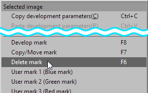
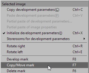
To reserve deletions, right click in either the thumbnail display or preview display, and select [Delete mark] from the context menu.
To delete multiple marked images for deletion together, select [Setting for marks] from the context menu.
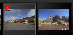 The “Delete mark” is the reservation mark to delete. When you put this mark, the image will not be deleted at this moment.
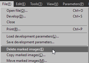 After attaching the “Delete mark” to all of the images which you want to delete, the menu command [File (F)]-[Delete marked images (E)] throws away the marked images to the Trash box.
If you hold down the [Shift] key at the same time, files will not be moved to Trash box, but will be completely deleted.
8.1.2. Delete selected images
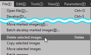 After selecting all of the images which you want to delete, the menu command [File (F)]-[Delete selected images] or [Delete] key throws away the selected images to the Trash box.
If you hold down the [Shift] key at the same time, files will not be moved to Trash box, but will be completely deleted.
8.2. Copy/Move Procedures
There are methods for copying and moving marked images and for copying and moving selected images.
Please see “8.3. Files to be Deleted, Copied, or Moved” for details on files that are to be copied or moved.
8.2.1. Copy/Move marked images
 One method for copying or moving images to another folder is to first mark images with a mark that reserves them to be copied / move, and then copy / move the images marked for copying / moving all together.
Utilize this method if you are sorting images that may be for copying / moving.
 The “Copy/Move mark” is the reservation mark to copy/move. When you put this mark, the image will not be copied/moved at this moment.
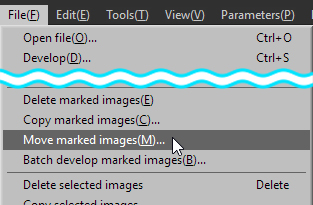 To move the marked images, execute [File (F)]-[Move marked images (M)] and then specify the folder into which the images are moved.
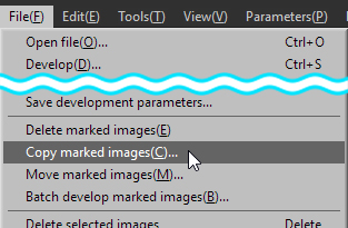 To copy the marked images, execute [File (F)]-[Copy marked images (C)] and then specify the folder into which the images are copied.
8.2.2. Copy/Move selected images
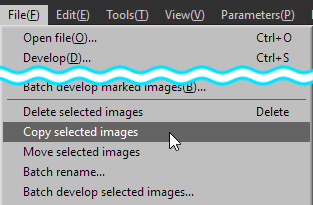 To copy/move the selected images, execute [File (F)]-[Copy selected image] or [Move selected image] and specify the folder into which the images are copied/moved.
Copying and moving selected images can be performed by dragging the selected thumbnail and dropping it into the “Folder” sub-control.
If the folder being copied / moved is a folder within the same volume, you can move it by dragging it without any key operations and copy it by dragging it while holding down the [Ctrl] key.
If the folder being copied / moved is to a different volume, you can drag and copy without any key operations and move it by dragging while holding down the [Shift] key.
8.3. Files to be Deleted, Copied, or Moved
Since this software is compatible with the DCF (Design rule for Camera File system) Standard which has been adopted into the most digital cameras, multiple files that have the same base name are handled as the identical group of images.
For example, if three files such as IMG_0001.RAW, IMG_0001.JPG, and IMG_0001.MOV exist in the same folder, these three files are handled as a group at the time of operation.
In other words, when you delete an IMG_0001, these three files are deleted as a group. So the same thing happens at the time of copying and moving.
However, if “Treat the same base name (file name without extension) files as a single image” under “Function settings” is OFF, only image files (RAW data, JPEG / TIFF images) are subject to operation.
In the DCF Standard, it is prescribed that the files that have the same base name are handled as a group.
For example, the file is composed in the output media as follows by the camera which is being based on this standard.
- IMG_0002.RAW … RAW file
- IMG_0002.JPG … JPG file created with RAW file simultaneously
- IMAG0002.THM … Thumbnail file
- IMAG0002.WAV … Sound clip associated with image
SILKYPIX Developer Studio Pro9 / 9 creates a working file for an image and handles it as a part of the group.
This software records and saves development parameters in a file named IMAG0002.RAW.9.SPD in the sub-folder “SILKYPIX_DS.” These files created in the “SILKYPIX_DS” sub-folder are for file operations.
Temporary files can also be deleted, copied and moved. Files with “.spi” extensions may be deleted, copied or moved at the same time. These are temporary files. Temporary files are deleted, copied or moved within the Temporary Folder. In this way, for example, when you copy or move a file, you do not have to recreate a temporary file, but just use it after it has been moved.
If you move or copy a file using a utility other than this software, files under “SILKYPIX_DS” are not treated as a set, so please be aware that development parameters accompanying images are not copied.
* When using the Spotting tool, files with an “.SPF” extension will be created, and when using the Partial correction tool, files with an “.SPB” extension will be created at the same time. These files will also reflect file operations.
8.4. Rename/Batch rename
The following two methods are functions for renaming file names of images for editing.
Rename
You can use this function when one image is selected in the thumbnail mode or the combination mode.Batch rename
You can use this function when multiple images are selected in the thumbnail mode or the combination mode.
When you rename a file, the following rule is applied to the both cases Rename/Batch rename.
Only a base name (a file name without extension) can be renamed. The extension cannot be renamed.
Files that have the same base name with a different extension and exist in the same folder are renamed simultaneously.
However, if “Treat the same base name (file name without extension) files as a single image” under “Function settings” is OFF, only image files (RAW data, JPEG / TIFF images) are subject to operation.
8.4.1. Rename
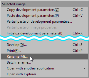 When an image is selected in the thumbnail mode, right click to display the context menu. Then select [Rename (M)] to display the “Rename” dialog.
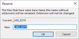 You can rename the file by inputting the base name that you want to use in the control box.
8.4.2. Batch rename
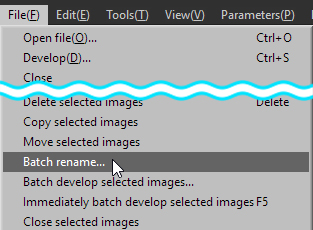 When some images are selected in the thumbnail mode or the combination mode, the menu [File (F)]-[Batch rename] displays the “Batch rename” dialog.
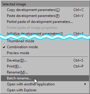 You can also display the “Batch rename” dialog by selecting [Batch rename] in the context menu. By inputting the base name that you want to use in this dialog, you can rename the files that have the same base name and exist in the same folder collectively.
Setting Rename Rule
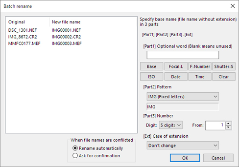
Specify basename in each 3 parts, “[Part1]“, “[Part2]“, and “[Part3].”[Part1]
Specifies optional word.
You can use control characters. (*)[Part2]
Selects from the prepared word.[Part3]
Specifies digit number of sequential number and the first figure.
When the control character area A is used, [Base], [Focal length], [F number], [Shutter speed], [ISO speed], [Date], and [Time] button input the corresponding control character automatically.
When the [Default] button is clicked, “Part1” is initialized. The control character can be inputted directly from your keyboard using conventional name.* There are the control characters for batch rename. (This is the same control character as for “Default filename to save”.)
%N : Basename of the RAW data file (“Basename” means a part of filename except the extension)
%L : Focal Length
%F : F Number
%T : Shutter Speed
%I : ISO Speed
%Y : Date Time - Year (2 digit)
%y : Date Time - Year (4 digit)
%M : Date Time - Month
%D : Date Time - Day
%h : Date Time - Hour
%m : Date Time - Minute
%s : Date Time - Seconds
%% : Method of describing ‘%’
Processing the same file name
When the same filename exists even after being renamed, you can select either to expand the file name automatically or display the confirm dialog every time.Specifying letter case of extension
Specify to use capital letters or small letters for an extension. You can specify either not to change the current extension or change into capital letters or small letters.
Batch rename Dialog
8.5. Printing
 This function prints selected images on a printer.
This function has two printing formats, one is “Normal printing” that prints one image on one sheet, the other is “Contact sheet” that prints multiple images on one sheet.
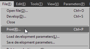
The menu command [File (F)]-[Print (R)] displays the “Print” dialog.
8.5.1. Basic Setting
8.5.1.1. Print format
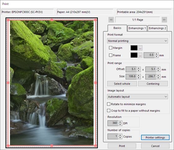
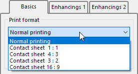 You can specify the print format. There are two different formats, one is “Normal printing” that prints one image on one sheet, and the other is “Contact sheet” that prints multiple images on one sheet.
If you select “Contact sheet”, you can select the aspect ratio of the frame for each image, which is 1:1, 4:3, 3:2, or 16:9.
In the print previews, printing that can be performed is the “Printable area,” for the paper whose white range is currently set.
The range of oblique lines shown bordering the paper is the “Edge” set on the printer.
As the “Edge” is the range occupied by the printer, this range cannot be printed.
In addition, when settings are changed to “Borderless” in the printer properties, that range is also included in the “Printable area.”
Under normal printing, the printing range of the image within the “Printable area” is the “Print range frame,” shown in a light orange.
In the contact sheet, the “Printing range frame” for each image is displayed in a light purple.
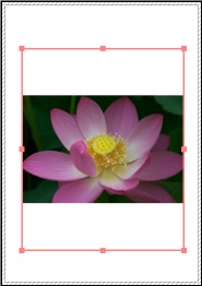
Normal printing
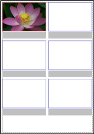
Contact sheet (4:3)
[Setting for Normal printing]
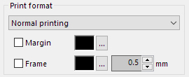
Margin
When this is checked, you can add a color to the margins of the printable area.
The “Color Selection” window opens when you click .
.
After adjusting colors with the slider or color circle, the color is set when you click the [OK] button.Frame
When checked, you can attach a frame line to the image within the printing range frame.
The “Color Selection” window opens when you click.
After adjusting colors with the slider or color circle, when you click the [OK] button the color is determined.
Designate the size of the frame lines in mm units.
[Settings for contact sheets]
Number of Horizontal Count
When the contact sheet is selected, you can specify the number of images to be located on one horizontal line, the range is between 2-20 images.Maximum height of text
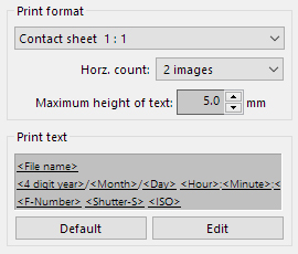
The character size is automatically adjusted to match the size of the printing area per image, but you can set an upper limit to the size here.Print text settings
Set texts located under the image.
Initial settings print in three rows as in the figure to the right: “Filename”; Date and time file shot or updated (“4 digit year,” “Month,” “Day,” “Hour,” “Minute,” “Second”), “F Number Shutter,” “Shutter Speed,” and “ISO speed.”Initialize
Return to the initial conditions of printing texts set by clicking on .
.
8.5.1.1.1. Editing print text
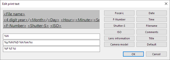
Open the “Edit print text” window and set text displayed on the contact sheet.
Click on
 and open the “Edit print text” window.
After clicking on the position which arranges items to be used in the edit box at the bottom left of the window, click the button for the item you will use.
The control characters for the item selected in (1) will be displayed in the edit box.
Control characters that can be displayed are as follows.[List of control characters]
%L : Focal Length
%F : F Number
%T : Sutter Speed
%I : ISO Speed
%l : Lens information
%c : Camera model
%Y : Date Time - Year (2 digit)
%y : Date Time - Year (4 digit)
%M : Date Time - Month
%D : Date Time - Day
%h : Date Time - Hour
%m : Date Time - Minute
%s : Date Time - Seconds
%n : Filename
%C : Comment
%t : Title
In addition to settings with item buttons, you can display character strings by inputting them directly in the edit box.
Click
to return to the defalt.If the image contents for the print character string at the top of the edit box are correct, click the [OK] button.
If you click the [Cancel] button, you will return to the “Print” page without the new contents reflected.
8.5.1.2. Print range
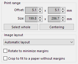 You can specify the print range if you select “Normal printing”.
Offset
Please specify the offset from the top left of the sheet.Size
Please specify the offset from the top left of the sheet.Select whole
It makes a print area the whole sheet.Centering
It puts a print area in the center in the sheet.
8.5.1.3. Image layout
8.5.1.3.1. Automatic layout
You can specify how to arrange the location of each image in the print area.
[Rotate to minimize margins]
If you enable this feature, the image is automatically rotated to minimize the borders.[Crop to fit to a paper without margins]
If you disable this feature, the image is placed fully within the print frame. It usually result in a border area left at the side of the image.
If you enable this feature, the image is fully filling out the area of the print frame. The image will be trimmed usually.
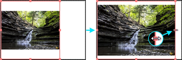
8.5.1.3.2. Arbitrary layout
Set the location of the image within the printing area.
You can change numerical values of magnification and offset and make adjustments to position with the controls, but you can also adjust positions by sight through direct operations on the preview image.
[Operations on the preview image]
You can perform operations similar to “Zoom tool”.Offset adjustments
Drag and move the image.Adjust magnification
Adjust magnification with [Shift] key + dragging.
8.5.1.4. Print image
When the printing format is set to “Normal printing,” you can adjust the printing range directly on the image for printing by dragging the printing range frame anchor shown on the image for printing.
8.5.1.5. Other
Resolution
SILKYPIX Developer Studio Pro9 / 9 expands/reduces an image according to the print resolution, which is sent to the printer. If you set larger value, SILKYPIX Developer Studio Pro9 / 9 makes larger image which is sent to the printer.
The larger value makes the better quality of printing but makes larger image data and required larger memory.Number of copies
You can specify the number of copies here.Printer settings
When the “Printer settings” button is clicked, the OS standard the “Print Setup” dialog will be displayed.
8.5.2. Enhancings 1
8.5.2.1. Color management
There are two formats of color management for printers on SILKYPIX.
If you do not understand “Color management”, select “Color management on printer side” and select “sRGB” as the print color space.
This is the standard setting if color management is not to be performed.
Please refer to “10.4.5.5. Color management for print output” concerning color management.
8.5.2.1.1. Perform color management
This is a method that sends data converted to Print Color Space by SILKYPIX to the printer and prints it.
If you print using this format, you must not make any color corrections on your printer.
Select a mode such as “No color corrections” and be sure to not perform any color conversions on your printer.
Please refer to your printer manual concerning printer settings.
This is a method for quite easily performing color management on a PC environment in which you can choose an appropriate “print color space.”
Work color space
Designate a color space for SILKYPIX to perform development processing.
Choose either sRGB or Adobe RGB.Print color space
Display a list of color spaces (= color profiles) installed on your OS.
Select an appropriate color space from this list.
The color space you should choose is determined by the combination of printer and paper you use.
However, the print color space that can be used by SILKYPIX must be RGB.
Please note that color spaces other than RGB, such as CMYK, cannot be used. (*1)
Depending on the model of the printer, there may be cases in which the printer maker offers a color profile (= ICC profile) for the printer.
There are also cases in which the paper manufacturer offers a color profile for a paper and printer combination.
Please use a profile created with special calibration tools or the like. (*2)
The color profile must first be installed onto the OS.
If a color profile is installed on Windows, select a color profile from Explorer, right click and open the context menu.
Select “Install Profile”.*1 Generally, the color space of color profiles offered by manufacturers of inkjet printers for home use is RGB, so you can use this without any problems.
*2 SILKYPIX uses the color management function installed in your OS to perform color management.
Therefore, SILKYPIX cannot use color profiles of a format not supported by your OS.
Please refer to “10.4.5.3. Color management performed on SILKYPIX” for details.Matching method
Original colors are not necessarily maintained if converted to a print color space determined by SILKYPIX development results.
SILKYPIX development results are created in the sRGB or Adobe RGB color space designated by the work color space, but there may be colors expressed in this color space that cannot be reproduced in the print color space.
Therefore, color conversion is performed in case of a different color space, but results of color conversion differ depending on the following four matching methods.
Printing photographic images generally uses “Perception” or “Maintain relative color gamut.”
Choose a matching method appropriate to the photograph’s hues and your aims.Perception
Perform color conversion that stresses the visual relationships of colors such as continuity of gradation and hues.
The absolute coordination of colors is changed, but it has a visually natural finished.Saturation
Perform color conversion that stresses saturation.
Choose this if your aim is to maintain high saturation more so than color reproduction.Maintain relative color gamut (Default setting)
This performs color conversion that maintains relative color relationships that stress hues and gradation.
Colors that cannot be found in the designated color space are adjusted to the closest colors that can be reproduced.Maintain absolute color gamut
This converts colors while maintaining the color’s absolute coordinates.
Colors that cannot be found in the designated color space are clipped. Choose this to express correct absolute colors.
8.5.2.1.2. Color management on printer side
Color management is performed by SILKYPIX even if this format is selected.
The SILKYPIX output is converted to the sRGB or Adobe RGB color space.
Select this mode for the following cases.
When you do not fully understand “Color management”
When you use the printer’s “Automatic correction” function or similar
When the color profile for the printer you use is not provided by the maker
When SILKYPIX is not compatible because the print color space on a special printer such as that for commercial use is something other than RGB
With this format, SILKYPIX sends an image converted to a print color space designated by sRGB or Adobe RGB to the printer.
If you are not sure, choose “sRGB” from “Print color space.” (*1)
You must make appropriate color management settings on your printer if you perform appropriate color management with this format.
Please refer to your printer manual concerning printer settings.
*1 Generally, inkjet printers for home use are adjusted for printing sRGB images.
Be sure to make appropriate settings on your printer if the SILKYPIX print color space is set to “Adobe RGB.”
If the printer is set to “sRGB” and the SILKYPIX print color space is set to “Adobe RGB,” printed colors will be light.
8.5.3. Enhancings 2
“Enhancings 2” is ON only when “Normal printing” is selected.
8.5.3.1. Unsharp mask
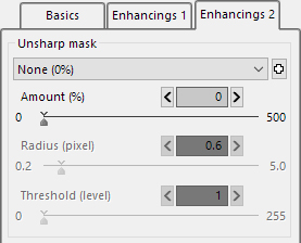 This is an adjustment item in effect only under “Normal printing”. Use if you want to perform additional unsharp mask when printing (Outline emphasis processing: A type of sharpness processing).
Please use this feature apart from the sharpness of the development parameter if you want to make up the sharpness to measure up to the blur of printing. The “sharpening” of the development parameter should be adjusted for each image to increase resolution.
On the other hand, the “Unsharp mask” set here has the same effect on all images printed at the same time, so it will compensate lowered resolution from ink runs that occur during the printing process.
Please refer to ‘10.1.9. Proper Use of Sharp in Development Parameters and Unsharp Mask when Developing / Printing’ for more details.
There are three types of adjustment items. You can adjust in terms of amount(%), radius(pixel) and threshold(level).
Amount
You can specify the “amount” to apply “unsharp mask”. The larger value makes the stronger sharpness.Radius
It sets the thickness of the edge of the outline emphasized.
The larger value makes the thicker edge, and the smaller value makes the thinner edge.
Typically, setting the range between 0.5-1.0 is recommended.Threshold
If the value is set smaller, the outlines are emphasized regardless of the clearness of the edge.
If the value is set larger, only the outlines are emphasized which has clear edge.
You can prevent the emphasis of the noise with this parameter.
Typically it is set to ‘1’. Please adjust this parameter to balance noise and sharpness.
8.5.3.2. Imprint data
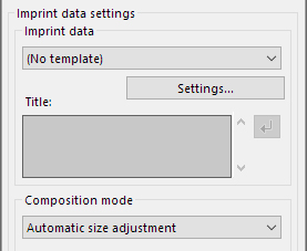 This item is effective only for normal printing. You can imprint the date and time the photograph was taken when printing.
In addition to the date and time the photograph was taken, you can also include image information, optional characters and credit images on the development results.
You can imprint the date and time the photograph was taken and image information by selecting prepared data for imprint data.
Creating “Imprint data” is required for imprinting a credit image you prepared.
Only JPEG and TIFF images can be selected as images to be imprinted.
Semitransparent images are also compatible with imprinting because it is compatible with TIFF with transparent color information.
Imprint data
Select which data for imprint data you will use.Settings
Make settings of data for imprint data.
Please refer to “9.7. Imprint data settings” for details.Composition mode
Select which data for imprint data you will compose.
For printing and develop, select the appropriate composition mode while looking at the preview display.Automatic size adjustment
Resize the composed characters and image to meet the output printed image size.
This adjusts so that the relative size is maintained.
Normally, this setting is used.Composite by the fixed-size
Compose keeping the designated size of the composed characters and image as is.
Use when the size of characters to be imprinted during printing is fixed.
Edit data for imprint data if the position of the characters and image to be imprinted is not appropriate.
8.6. Print Preview of Multiple Images
If you select multiple images in the thumbnail mode or the combination mode, you will print multiple pages as one copy.
In this case, you can change preview page by clicking the buttons, which are located in both sides of the page area.
8.7. Plug-ins
SILKYPIX Developer Studio Pro9 / 9 is compatible with plug-ins.
When a separate plug-in is installed, the plug-in icon  is displayed in the toolbar. They are added from [File (F)]-[Plug-ins] in the menu.
By selecting an image from the thumbnail display and selecting a plug-in, you can process the selected image using the function with the extension of the plug-in.
8.8. Open with another application
With this software, you can register other applications in advance to develop selected images and open them directly via operation of this software alone. (*1, *2)
*1 The applications must support the specified file format.
Whether multiple images can be opened simultaneously varies according to the applications.*2 Up to 10 applications can be registered.
8.8.1. Register applications
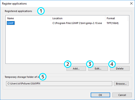
The menu command [File (F)]-[Open with another application] displays the “Register applications” dialog.
You can also display the “Register applications” dialog from the context menu that is displayed by right-clicking on a preview or thumbnail, and the menu that is displayed by clicking the ![]() icon on the toolbar.
icon on the toolbar.
Registered applications
A list of pre-registered applications is displayed.Add
Register a new application.Edit
Edit settings for a registered application.Delete
Delete the settings of a registered application.Temporary storage folder of images
Specify a folder to temporarily save development results when opening an image in another application.
For both Windows and macOS, the “SILKYPIX” folder under the “Picture” folder in each user folder is set by default.
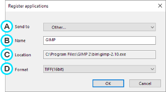 Clicking [Add…] will display a dialog for specifying an application.
(A) Send to
Select any application from the list.
If no application is shown in the list, select “Other…” and specify an application (.exe file) directly.(B) Name
Set the name that will be shown in the list of registered applications.
The application name or file name selected in Send to will be set, so change it as needed.(C) Location
The pathname of the selected application will be shown.(D) Format
Select the file format in which to open a developed image in another application.
Choose from TIFF(16bit), TIFF(8bit), and JPEG. (*)
* TIFF (16bit, 8bit) will be developed without compression, and JPEG in Quality of 100.
8.8.2. Open selected images with another application
 Select a registered application from any of the following menus.
- Select from [File(F)]-[Open with another application]
- Select from “Open with another application” in the context menu that is displayed by right-clicking on a preview or thumbnail
- Select from the menu that is displayed by clicking the
 icon in the toolbar
The selected image will be developed, and the developed image will open in the specified application.