| SILKYPIX® Developer Studio 4.0 | SOFTWARE MANUAL |
| 8. File Operation | ||||||||
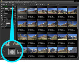 This software supports operations to delete, copy and move the scene which is displayed in the thumbnail mode or the combination mode.
8.1. Delete Procedures
Scenes can be deleted either by a method of deleting scenes reserved for deletion or by a method of deleting selected scenes.
With either method, the default operation is to move scenes to Trash. In other words, scenes are not completely deleted and can later be returned to their original file from the Trash. (*)
If you wish to completely delete a scene, enter a command from the menu or with the short cut key while pushing the [SHIFT] key.
 8.1.1. Delete Reserved Scene
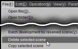 After selecting all of the scenes which you want to delete, the menu command [File(F)]-[Delete selected scene] or [Delete] key throws away the selected scenes to the trash box.
If you hold down the [SHIFT] key at the same time, files will not be moved to Trash, but will be completely deleted.
With either method, the default operation is to move scenes to Trash. In other words, scenes are not completely deleted and can later be returned to their original file from the Trash. (*)
If you wish to completely delete a scene, enter a command from the menu or with the short cut key while pushing the [SHIFT] key.
| * | Files on drives that do not have Trash, such as external HDDs and network drives, cannot be moved to Trash and are deleted. Please be careful. |
8.1.1. Delete Reserved Scene One method for deleting scenes is to first mark scenes to be deleted with a mark that reserves them for deletion, and then delete the scenes reserved for deletion all together.
Utilize this method if you are sorting scenes that may be considered for deletion.
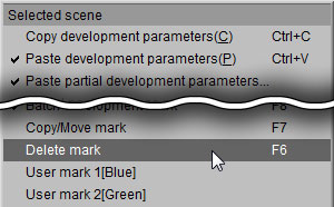
To reserve deletions, right click in either the thumbnail display or preview display, and select [Reserve deletions] from the context menu.
To delete multiple reserved scenes for deletion together, select [Reserved / marked settings] from the context menu.
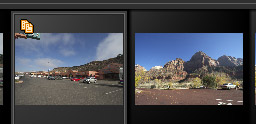
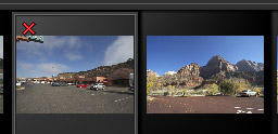 The "delete mark" is the reservation mark to delete. When you put this mark, the scene will not be deleted at this moment.
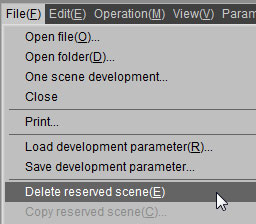 After attaching the "delete mark" to all of the scenes which you want to delete, the menu command [File(F)]-[Delete reserved scene] throws away the marked scenes to the trash box.
If you hold down the [SHIFT] key at the same time, files will not be moved to Trash, but will be completely deleted.
8.1.2. Delete Selected Scene Utilize this method if you are sorting scenes that may be considered for deletion.
To reserve deletions, right click in either the thumbnail display or preview display, and select [Reserve deletions] from the context menu.
To delete multiple reserved scenes for deletion together, select [Reserved / marked settings] from the context menu.
The "delete mark" is the reservation mark to delete. When you put this mark, the scene will not be deleted at this moment.After attaching the "delete mark" to all of the scenes which you want to delete, the menu command [File(F)]-[Delete reserved scene] throws away the marked scenes to the trash box.If you hold down the [SHIFT] key at the same time, files will not be moved to Trash, but will be completely deleted.
After selecting all of the scenes which you want to delete, the menu command [File(F)]-[Delete selected scene] or [Delete] key throws away the selected scenes to the trash box.If you hold down the [SHIFT] key at the same time, files will not be moved to Trash, but will be completely deleted.
8.2. Copy/Move Procedures
 8.2.1. Copy/Move Reserved Scene
 One method for copying or moving scenes to another folder is to first mark scenes with a mark that reserves them to be copied / move, and then copy / move the scenes reserved for copying / moving all together.
Utilize this method if you are sorting scenes that may be for copying / moving.
 The "copy/move mark" is the reservation mark to copy/move. When you put this mark, the scene will not be copied/moved at this moment.
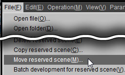 To move the marked scenes, execute [File(F)]-[Move reserved scene] and then specify the folder into which the scenes are moved.
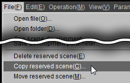 To copy the marked scenes, execute [File(F)]-[Copy reserved scene] and then specify the folder into which the scenes are copied.
8.2.2. Copy/Move Selected Scene Utilize this method if you are sorting scenes that may be for copying / moving.
The "copy/move mark" is the reservation mark to copy/move. When you put this mark, the scene will not be copied/moved at this moment.To move the marked scenes, execute [File(F)]-[Move reserved scene] and then specify the folder into which the scenes are moved.To copy the marked scenes, execute [File(F)]-[Copy reserved scene] and then specify the folder into which the scenes are copied. To copy/move the selected scenes, execute [File(F)]-[Copy selected scene] or [Move selected scene] and specify the folder into which the scenes are copied/moved.
8.3. Files to be Deleted, Copied, or Moved
Since this software is compatible with the DCF (Design rule for Camera File system) Standard which has been adopted into the most digital cameras, multiple files that have the same base name are handled as the identical group of images.
For example, if three files such as IMG_0001.RAW, IMG_0001.JPG, and IMG_0001.MOV exist in the same folder, these three files are handled as a group at the time of operation.
In other words, when you delete an IMG_0001, these three files are deleted as a group. So the same thing happens at the time of copying and moving.
In the DCF Standard, it is prescribed that the files that have the same base name are handled as a group.
For example, the file is composed in the output media as follows by the camera which is being based on this standard.
IMG_0002.RAW ... RAW file
IMG_0002.JPG ... JPG file created with RAW file simultaneously
IMAG0002.THM ... Thumbnail file
IMAG0002.WAV ... Sound clip associated with scene
SILKYPIX® Developer Studio 4.0 writes the development parameters in the file named "IMG_0002.RAW.SPD" and a thumbnail file "IMG_0002.RAW.SPI" into the "SILKYPIX_DS" sub-folder.
These files created into the "SILKYPIX_DS" sub-folder are treated as members of the group, too.
You can treat these files as a group by other utility which was based on the DCF standard, too. But please remember that if you modify this files with another application, the files created into the "SILKYPIX_DS" sub-folder by SILKYPIX® Developer Studio 4.0 will not be handled as a group.
8.4. Rename/Batch Rename
The following two methods are functions for renaming file names of images for editing.
When you rename a file, the following rule is applied to the both cases Rename/Batch rename.
 8.4.1. Rename
 8.4.2. Batch rename
| (1) | Rename |
You can use this function when one scene is selected in the thumbnail mode or the combination mode.
| (2) | Batch rename |
You can use this function when multiple scenes are selected in the thumbnail mode or the combination mode.
| (1) | Only a base name (a file name without extension) can be renamed. The extension cannot be renamed. |
| (2) | Files that have the same base name with a different extension and exist in the same folder are renamed simultaneously. |
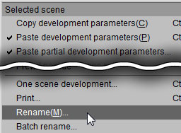
8.4.1. Rename When a scene is selected in the thumbnail mode, right click to display the context menu. Then select [Rename (M)] to display the "Rename" dialog.
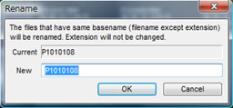 You can rename the file by inputting the base name that you want to use in the control box.
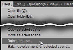
You can rename the file by inputting the base name that you want to use in the control box. 8.4.2. Batch rename When some scenes are selected in the thumbnail mode or the combination mode, the menu [File(F)]-[Batch Rename] displays the "Batch rename" dialog.
 You can also display the "Batch rename" dialog by selecting [Batch rename] in the context menu. By inputting the base name that you want to use in this dialog, you can rename the files that have the same base name and exist in the same folder collectively.
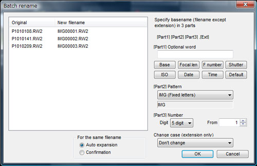
You can also display the "Batch rename" dialog by selecting [Batch rename] in the context menu. By inputting the base name that you want to use in this dialog, you can rename the files that have the same base name and exist in the same folder collectively. | (1) | Setting Rename Rule |
Specify basename in each 3 parts, "[Part1]", "[Part2]", and "[Part3]."
When the control character area A is used, [Base], [Focal lengthen], [F number], [Shutter speed], [ISO speed], [Date], and [Time] button input the corresponding control character automatically.
When the [Default] button is clicked, area A is initialized. The control character can be inputted directly from your keyboard using conventional name.
| [Part1] | Specifies optional word. You can use control characters. (*) |
| [Part2] | Selects from the prepared word. |
| [Part3] | Specifies digit number of sequential number and the first figure. |
When the [Default] button is clicked, area A is initialized. The control character can be inputted directly from your keyboard using conventional name.
| * | There are the control characters for batch rename. (This is the same control character as for "Default filename to save".) |
| %N | Basename of the RAW data file ("Basename" means a part of filename except the extension) |
| %L | Focal Length |
| %F | F Number |
| %T | Shutter Speed |
| %I | ISO Speed |
| %Y | Date Time - Year (2 digit) |
| %y | Date Time - Year (4 digit) |
| %M | Date Time - Month |
| %D | Date Time - Day |
| %h | Date Time - Hour |
| %m | Date Time - Minute |
| %s | Date Time - Seconds |
| %% | Method of describing '%' |
| (2) | Processing the same file name |
When the same filename exists even after being renamed, you can select either to expand the file name automatically or display the confirm dialog every time.
| (3) | Specifying letter case of extension |
Specify to use capital letters or small letters for an extension. You can specify either not to change the current extension or change into capital letters or small letters.
 Batch rename Dialog |
8.5. Printing
 This function prints selected scenes on a printer.
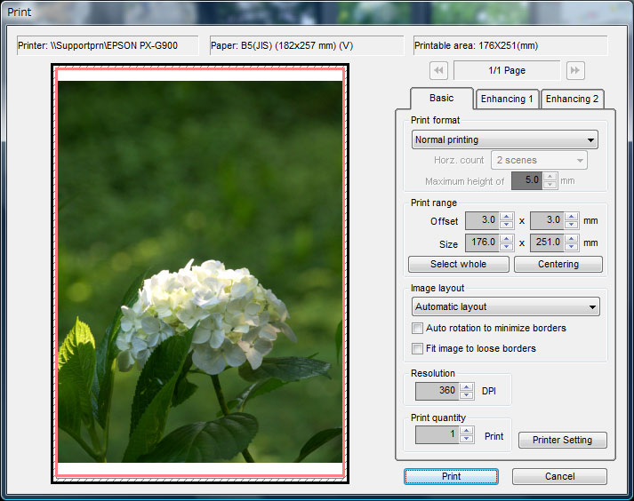
This function has two printing formats, one is "Normal printing" that prints one scene on one sheet, the other is "Contact sheet" that prints multiple scenes on one sheet.
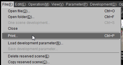
The menu command [File(F)]-[Print(P)] displays the "Print" dialog.
 |
 8.5.1. Basic Setting
 8.5.1.1. Print Format
 8.5.1.2. Print Range
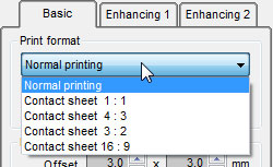
You can specify the print format. There are 2 different formats, one is "Normal printing" that prints one scene on one sheet, and the other is "Contact sheet" that prints multiple scenes on one sheet.
If you select "Contact sheet", you can select the aspect ratio of the frame for each scene, which is 1:1, 4:3, 3:2, or 16:9.
[Settings for contact sheets]
If you select "Contact sheet", you can select the aspect ratio of the frame for each scene, which is 1:1, 4:3, 3:2, or 16:9.
[Settings for contact sheets]
| Number of Horizontal Scenes | When the contact sheet is selected, you can specify the number of scenes to be located on one horizontal line, the range is between 2-20 scenes. |
| Maximum size of characters | The character size is automatically adjusted to match the size of the printing area per scene, but you can set an upper limit to the size here. |
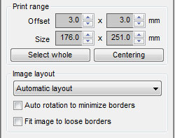
8.5.1.2. Print Range You can specify the print range if you select "Normal printing".
8.5.1.3. Image arrangement | Top left | Please specify the offset from the top left of the sheet. |
| Size | Please specify the offset from the top left of the sheet. |
| Select whole | It makes a print area the whole sheet. |
| Centering | It puts a print area in the center in the sheet. |
8.5.1.3.1. Automatic arrangement
You can specify how to arrange the location of each scene in the print area.
You can specify how to arrange the location of each scene in the print area.
| (1) | [Auto rotation to minimize borders] |
If you enable this feature, the image is automatically rotated to minimize the borders.
| (2) | [Fit image to loose border] |
If you disable this feature, the image is placed fully within the print frame. It usually result in a border area left at the side of the image.
If you enable this feature, the image is fully filling out the area of the print frame. The image will be trimmed usually.
If you enable this feature, the image is fully filling out the area of the print frame. The image will be trimmed usually.
8.5.1.4. Other
8.5.2. Expanded settings 1 | Resolution | SILKYPIX® Developer Studio 4.0 expands/reduces an image according to the print resolution, which is sent to the printer. If you set larger value, SILKYPIX® Developer Studio 4.0 makes larger image which is sent to the printer. The larger value makes the better quality of printing but makes larger image data and required larger memory. |
| Print Quantity | You can specify the number of copies here. |
| Printer Setting | When the "Printer Setting" button is clicked, the OS standard the "Printer Setting" dialog will be displayed. |
8.5.2.1. Color management
8.5.3. Expanded settings 2 There are two formats of color management for printers on SILKYPIX.
If you do not understand "Color management", select "Color management on the printer side" and select "sRGB" as the print color space.
This is the standard setting if color management is not to be performed.
Please refer to "10.4.5.5. Color management for printer output" concerning color management.
8.5.2.1.1. Perform color management
This is a method that sends data converted to Print Color Space by SILKYPIX to the printer and prints it.
If you print using this format, you must not make any color corrections on your printer. Select a mode such as "No color corrections" and be sure to not perform any color conversions on your printer.
Please refer to your printer manual concerning printer settings.
This is a method for quite easily performing color management on a PC environment in which you can choose an appropriate "print color space."
Color management is performed by SILKYPIX even if this format is selected. The SILKYPIX output is converted to the sRGB or Adobe RGB color space.
Select this mode for the following cases.
With this format, SILKYPIX sends an image converted to a print color space designated by sRGB or Adobe RGB to the printer.
If you are not sure, choose "sRGB" from "Print color space."(*1)
You must make appropriate color management settings on your printer if you perform appropriate color management with this format.
Please refer to your printer manual concerning printer settings.
If you do not understand "Color management", select "Color management on the printer side" and select "sRGB" as the print color space.
This is the standard setting if color management is not to be performed.
Please refer to "10.4.5.5. Color management for printer output" concerning color management.
8.5.2.1.1. Perform color management
This is a method that sends data converted to Print Color Space by SILKYPIX to the printer and prints it.
If you print using this format, you must not make any color corrections on your printer. Select a mode such as "No color corrections" and be sure to not perform any color conversions on your printer.
Please refer to your printer manual concerning printer settings.
This is a method for quite easily performing color management on a PC environment in which you can choose an appropriate "print color space."
| (1) | Work color space |
Designate a color space for SILKYPIX to perform development processing.
Choose either sRGB or Adobe RGB.
Choose either sRGB or Adobe RGB.
| (2) | Print color space |
Display a list of color spaces (= color profiles) installed on your OS. Select an appropriate color space from this list.
The color space you should choose is determined by the combination of printer and paper you use.
However, the print color space that can be used by SILKYPIX must be RGB. Please note that color spaces other than RGB, such as CMYK, cannot be used. (*1)
Depending on the model of the printer, there may be cases in which the printer maker offers a color profile (= ICC profile) for the printer.
There are also cases in which the paper manufacturer offers a color profile for a paper and printer combination.
Please use a profile created with special calibration tools or the like.(*2)
The color profile must first be installed onto the OS.
If a color profile is installed on Windows (Vista / 7 / 8 / 8.1), select a color profile from Explorer, right click and open the context menu. Select "Install Profile."
| *1 | Generally, the color space of color profiles offered by manufacturers of inkjet printers for home use is RGB, so you can use this without any problems. |
| *2 | SILKYPIX uses the color management function installed in your OS to perform color management. Therefore, SILKYPIX cannot use color profiles of a format not supported by your OS. Please refer to "Color profiles compatible with SILKYPIX" for details. |
| (3) | Matching method |
Original colors are not necessarily maintained if converted to a print color space determined by SILKYPIX development results.
SILKYPIX development results are created in the sRGB or Adobe RGB color space designated by the work color space, but there may be colors expressed in this color space that cannot be reproduced in the print color space.
Therefore, color conversion is performed in case of a different color space, but results of color conversion differ depending on the following four matching methods.
Printing photographic images generally uses "Perception" or "Maintain relative color gamut." Choose a matching method appropriate to the photograph's hues and your aims.
8.5.2.1.2. Color management on the printer side SILKYPIX development results are created in the sRGB or Adobe RGB color space designated by the work color space, but there may be colors expressed in this color space that cannot be reproduced in the print color space.
Therefore, color conversion is performed in case of a different color space, but results of color conversion differ depending on the following four matching methods.
Printing photographic images generally uses "Perception" or "Maintain relative color gamut." Choose a matching method appropriate to the photograph's hues and your aims.
| Perception | Perform color conversion that stresses the visual relationships of colors such as continuity of gradation and hues. The absolute coordination of colors is changed, but it has a visually natural finished. |
| Saturation | Perform color conversion that stresses saturation. Choose this if your aim is to maintain high saturation more so than color reproduction. |
| Maintain relative color gamut (Default setting) | This performs color conversion that maintains relative color relationships that stress hues and gradation. Colors that cannot be found in the designated color space are adjusted to the closest colors that can be reproduced. |
| Maintain absolute color gamut | This converts colors while maintaining the color's absolute coordinates. Colors that cannot be found in the designated color space are clipped. Choose this to express correct absolute colors. |
Color management is performed by SILKYPIX even if this format is selected. The SILKYPIX output is converted to the sRGB or Adobe RGB color space.
Select this mode for the following cases.
| (1) | When you do not fully understand "Color management" |
| (2) | When you use the printer's "Automatic correction" function or similar |
| (3) | When the color profile for the printer you use is not provided by the maker |
| (4) | When SILKYPIX is not compatible because the print color space on a special printer such as that for commercial use is something other than RGB |
With this format, SILKYPIX sends an image converted to a print color space designated by sRGB or Adobe RGB to the printer.
If you are not sure, choose "sRGB" from "Print color space."(*1)
You must make appropriate color management settings on your printer if you perform appropriate color management with this format.
Please refer to your printer manual concerning printer settings.
| *1 | Generally, inkjet printers for home use are adjusted for printing sRGB images. Be sure to make appropriate settings on your printer if the SILKYPIX print color space is set to "Adobe RGB." If the printer is set to "sRGB" and the SILKYPIX print color space is set to "Adobe RGB," printed colors will be light. |
8.5.3.1. Unsharp Mask
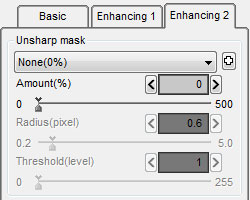 This feature additionally applies an unsharp mask filter to the developed image. You can adjust the unsharp mask filter with amount(%), radius(pixel) and threshold value(level).
Please use this feature apart from the sharpness of the development parameter if you want to make up the sharpness to measure up to the blur of printing.
The "sharpness" of the development parameter should be adjusted for each scene to increase resolution.
On the other hand, the "Unsharp mask" set here has the same effect on all scenes printed at the same time, so it will compensate lowered resolution from ink runs that occur during the printing process.
Please refer to '10.1.10 How to Use Sharp and Unsharp Mask' for more details.
There are three types of adjustment items. You can adjust in terms of amount (%), radius (pixel) and threshold value (level).
This feature additionally applies an unsharp mask filter to the developed image. You can adjust the unsharp mask filter with amount(%), radius(pixel) and threshold value(level).Please use this feature apart from the sharpness of the development parameter if you want to make up the sharpness to measure up to the blur of printing.
The "sharpness" of the development parameter should be adjusted for each scene to increase resolution.
On the other hand, the "Unsharp mask" set here has the same effect on all scenes printed at the same time, so it will compensate lowered resolution from ink runs that occur during the printing process.
Please refer to '10.1.10 How to Use Sharp and Unsharp Mask' for more details.
There are three types of adjustment items. You can adjust in terms of amount (%), radius (pixel) and threshold value (level).
| Amount | You can specify the "amount" to apply "unsharp mask". The larger value makes the stronger sharpness. |
| Radius | It sets the thickness of the edge of the outline emphasized. The larger value makes the thicker edge, and the smaller value makes the thinner edge. Typically, setting the range between 0.5-1.0 is recommended. |
| Threshold | If the value is set smaller, the outlines are emphasized regardless of the clearness of the edge. If the value is set larger, only the outlines are emphasized which has clear edge. You can prevent the emphasis of the noise with this parameter. Typically it is set to '1'. Please adjust this parameter to balance noise and sharpness. |
8.5.4. Print Preview of Multiple Scenes
If you select multiple scenes in the thumbnail mode or the combination mode, you will print multiple pages as one copy.
In this case, you can change preview page by clicking the buttons, which are located in both sides of the page area.
In this case, you can change preview page by clicking the buttons, which are located in both sides of the page area.