| SILKYPIX® Developer Studio 3.0 | SOFTWARE MANUAL |
| 4. How to Adjust Development Parameter | ||||||||
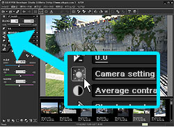
 Use the "Parameter control" to adjust development parameters. By default, the "Parameter control" appears at the left side of the screen. You can move its position to the right side with [Display Setting].
Further, you can change it to a floating window with the [Display setting].
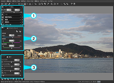
On the "Parameter control", there are the following 3 sections;
(1) "Main control section" which consists of some dropdown lists to select a taste (=preset value) and the "Exposure bias" slider control.
(2) "Tab page" which is an area for the sub-controls, which are selected on the "Parameter control".
(3) "Control box" which is an area for other sub-controls, hich are used to adjust an image more finely by setting specified values.
The "sub-control", which is located on "Tab page" or "Control box", is a control for selecting a value in each category of the development parameters. The sub-control can be displayed also as a floating window.
You can specify the setting of "Parameter control" by [Display setting], which appeares on the menu command [View(V)]-[Display setting].
And you can specify the setting of other sub-contorls by the above sub-controls that have a system menu, which is opened by a right-click of the title area.
As a basic workflow, set the level of theExposure bias with "Slider control" first, and then, select each "taste" of white balance, tone, color, and sharpness/noise reduction.
4.1 "Parameter Control" and "Sub-control"
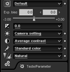 "Parameter control" has 3 sections. On the "Main control section" that is the top section, there are the following controls;
Taste/parameter (Dropdown list + Select button)
Exposure bias (Slider control)
Exposure bias (Dropdown list + Select button)
White balance (Dropdown list + Select button)
Tone (Dropdown list + Select button)
Color (Dropdown list + Select button)
Sharpness/Noise reduction (Dropdown list + Select button)
Development (Select button)
On the bottom area of the "Parameter control", there are 8 buttons to switch sub-controls that are for fine adjustment of the development parameter or displaying information.
"Dropdown list" is the GUI for selecting a taste (=preset value) that is prepared in advance by ISL (Ichikawa Soft Laboratory) or a user.
The "taste" is a value consisting of development parameter. About details of the "taste", please refer to '4.1.1 Taste'.
When you select a taste from the dropdown list, the related sub-controls automatically appear on the "Tab page". However, according to customer's preference, the sub-controls can be located on the "Control box" or a floating window.
4.1.1 Taste
"Taste" is a preset value that is defined by setting development parameters.
You can easily define a "taste" value for frequently-used development parameters.
[Usage-1: Selecting a taste from the dropdown list]
 The dropdown list for taste is the top dropdown list on "Main control section" of the "Parameter control" window.
When you select a taste from this dropdown list, the whole development parameter or partial development parameters are changed in the same way as "Paste partial development parameter".
Please remember the whole development parameter are not always changed.
[Explanation of display]
4.1.1.2 Other Dropdown List
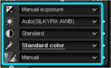 Except for the "dropdown list for Taste", there are five dropdown lists on the Main control, which are, from top to bottom, the dropdown list of "Exposure bias", "White balance", "Tone", "Color", and "Sharpness/noise reduction".
(Please refer to [The detail definition of taste])
When sub-controls of these dropdown lists are displayed on the floating window, each dropdown list is arranged at the top of the floating window. The parameter category of these dropdown lists is type (A).
 For type (B) parameter category of which dropdown list is used to finely adjust development parameters, the dropdown list is located at the top of the floating window.
[Target parameter category]
4.1.1.3 Customizing or Adding Taste
 You can customize and add a taste by the following ways;
Use the icon "Customize taste" or "Add new taste" on the "Taste/parameter" sub-control, or the icon "Add new taste" right side of each dropdown list.
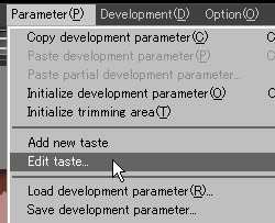
Or you can choose the menu command [Parameter(P)]-[Customize taste] or [Add new taste].
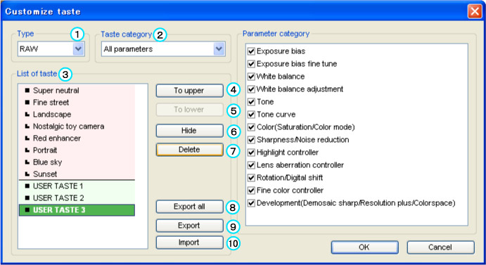
When you choose the "Customize taste", the "Customize taste" dialog box appears.
(1) Type of file
4.1.1.4 Applying Tastes to Multiple Scenes
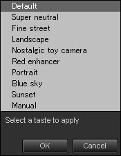 You can apply a taste to multiple scenes at the same time. In the "thumbnail mode" or "combination mode", when you select multiple scenes at the same time, the icon on the right side of the dropdown list changes to
 .
.
When you click this icon, the taste list opens. Select one taste to apply and click "OK", then the selected taste will be applied to all the selected scenes.
* If you selected many scenes at the same time, it may take long time for processing.
4.1.2 Taste/ParameterYou can easily define a "taste" value for frequently-used development parameters.
[Usage-1: Selecting a taste from the dropdown list]
Open a dropdown list and select a "taste". Then the development parameters that determine the taste are applied to an image.
There are two types of tastes or dropdown lists. One is defined by whole development parameter, and the other is defined by part of development parameters.
Please refer to '4.1.1.1 Dropdown List for Taste' and '4.1.1.2 Other Dropdown List'.
* It works in the same way as "Paste partial development parameter".
[Usage-2: Defining your favorite taste]There are two types of tastes or dropdown lists. One is defined by whole development parameter, and the other is defined by part of development parameters.
Please refer to '4.1.1.1 Dropdown List for Taste' and '4.1.1.2 Other Dropdown List'.
* It works in the same way as "Paste partial development parameter".
You can define a new taste by setting development parameters that are favored or frequently used by you. The definition is easily performed by using the "taste" function.
There are two types of tastes on the dropdown list. One is defined the whole development parameter , and the other is defined by part of the development parameters.
Please refer to '4.1.1.3 Customizing or Adding Taste'.
[The detail definition of taste]There are two types of tastes on the dropdown list. One is defined the whole development parameter , and the other is defined by part of the development parameters.
Please refer to '4.1.1.3 Customizing or Adding Taste'.
There are 3 kindsof tastes. The first one is defined by the whole development parameter, the second is by one category of development parameter, and the third is by some categories of development parameter.
There are the following 14 development-parameter categories, which are also used for "Paste partial development parameter" function.
Each development-parameter category has one sub-control to adjust the development parameters.
And there are 3 types of development-parameter categories, (A), (B) and (C).
(A) Exposure bias
(B) Exposure bias fine tune
(A) White balance
(B) White balance adjustment
(A) Tone
(B) Tone curve
(A) Color (saturation and color mode)
(A) Sharpness/noise reduction
(B) Highlight controller
(B) Lens aberration controller
(B) Rotation/digital shift
(B) Fine color controller
(A) Development (Demosaic sharp, resolution plus and colorspace)
(C) Trimming
(A) is the major parameter category type of which dropdown list is located on the "Parameter control".
(B) is the parameter category type that is used to finely adjust the development parameter with the sub-controls that are located on a floating window as default.
(C) is an exceptional category type which is not used for copying and pasting the development parameter. It is only used for "Paste partial development parameter" function.
Only the "dropdown list for Taste" can have all 3 types of parameter categories.
A "other dropdown list" can have only its related one development-parameter category.
4.1.1.1 Dropdown List for TasteThere are the following 14 development-parameter categories, which are also used for "Paste partial development parameter" function.
Each development-parameter category has one sub-control to adjust the development parameters.
And there are 3 types of development-parameter categories, (A), (B) and (C).
(A) Exposure bias
(B) Exposure bias fine tune
(A) White balance
(B) White balance adjustment
(A) Tone
(B) Tone curve
(A) Color (saturation and color mode)
(A) Sharpness/noise reduction
(B) Highlight controller
(B) Lens aberration controller
(B) Rotation/digital shift
(B) Fine color controller
(A) Development (Demosaic sharp, resolution plus and colorspace)
(C) Trimming
(A) is the major parameter category type of which dropdown list is located on the "Parameter control".
(B) is the parameter category type that is used to finely adjust the development parameter with the sub-controls that are located on a floating window as default.
(C) is an exceptional category type which is not used for copying and pasting the development parameter. It is only used for "Paste partial development parameter" function.
Only the "dropdown list for Taste" can have all 3 types of parameter categories.
A "other dropdown list" can have only its related one development-parameter category.
The dropdown list for taste is the top dropdown list on "Main control section" of the "Parameter control" window.When you select a taste from this dropdown list, the whole development parameter or partial development parameters are changed in the same way as "Paste partial development parameter".
Please remember the whole development parameter are not always changed.
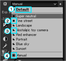
[Explanation of display]
(1) "The emphasized word with a under line" means default "taste". If the default "taste" is assigned from the existing "taste", the name of the existing taste is emphasized. If the default "taste" is not assigned from the existing "taste", the word "Default" is emphasized as shown on the explanation figure.
(2) This is a mark for the "whole taste".
(3) This is a mark for the "partial taste".
(4) This box mark means that this taste is selected now. For the case of "whole taste", one "whole taste" is marked with this mark. For the case of "partial taste", every taste belonging to the "partial taste" is marked with this mark.
[Whole taste and Partial taste](2) This is a mark for the "whole taste".
(3) This is a mark for the "partial taste".
(4) This box mark means that this taste is selected now. For the case of "whole taste", one "whole taste" is marked with this mark. For the case of "partial taste", every taste belonging to the "partial taste" is marked with this mark.
The "whole taste" is defined by the whole development parameter, and the "partial taste" is defined by part of development parameter.
You can distinguish these two types with the mark on the dropdown list.
[Taste list for selection]You can distinguish these two types with the mark on the dropdown list.
When you open the dropdown list, you can see and select the tastes on the list.
There are two kinds of tastes, one is "maker taste" prepared by ISL and the other is "user taste" defined by user.
And you can find "Default" and "Manual" on the list, which are not "taste". They have the following meanings;
[Display of the selected taste]There are two kinds of tastes, one is "maker taste" prepared by ISL and the other is "user taste" defined by user.
And you can find "Default" and "Manual" on the list, which are not "taste". They have the following meanings;
| Default | If you select it, the development parameters are reset to default. When you specified one of tastes as default, the word "Default" is not displayed on the list. In this case, the name of the specified taste is emphasized. |
| Manual | "Manual" is displayed when the current taste does not match other existing tastes or the default taste. Even if you select this taste, the development parameters will not be changed. |
When the dropdown list is closed, he name of the current taste is displayed.
When one of registered tastes is selected, the name of the selected taste is displayed. But the name of a partial taste is not displayed. Otherwise, "Default" or "Manual" is sometimes displayed.
When one of registered tastes is selected, the name of the selected taste is displayed. But the name of a partial taste is not displayed. Otherwise, "Default" or "Manual" is sometimes displayed.
| Default | "Default" is displayed when the development parameters of the current taste match those of the default. If the development parameters of a certain "whole taste" match those of the default, the name of the "whole taste" is displayed. |
| Manual | "Manual" is displayed when the development parameters of the current taste do not match those of any taste. |
| Manual(Taste applied) | "Manual (Taste applied)" is displayed when the development parameters of the current taste match those of a certain "partial taste". |
| * | "Partial taste" is not displayed because the development parameters of the current taste can match those of two or more partial tastes at the same time. The mark of the "Partial taste" is displayed only when the dropdown list is opened. |
Except for the "dropdown list for Taste", there are five dropdown lists on the Main control, which are, from top to bottom, the dropdown list of "Exposure bias", "White balance", "Tone", "Color", and "Sharpness/noise reduction". (Please refer to [The detail definition of taste])
When sub-controls of these dropdown lists are displayed on the floating window, each dropdown list is arranged at the top of the floating window. The parameter category of these dropdown lists is type (A).
For type (B) parameter category of which dropdown list is used to finely adjust development parameters, the dropdown list is located at the top of the floating window.[Target parameter category]
Each dropdown list has the tastes that belongs to a single parameter category. Selecting a taste on the dropdown list on the sub-control window affects only the development parameters of the same sub-control.(*1)
[Taste list for selection]| *1 | In the case of the "parameter control" dropdown list, the corresponding sub-controls are affected. |
| *2 | But Sharp/noise reduction control is exceptional. Its sub-controls are divided to two parts despite one parameter category. |
When you open the dropdown list, you can see and select the tastes on the list. There are two kinds of tastes, one is "maker taste" prepared by ISL and the other is "user taste" defined by user.
And you can find "Default" and "Manual" on the list, which are not "taste". have the following meanings;
[Display of the selected taste]And you can find "Default" and "Manual" on the list, which are not "taste". have the following meanings;
| Default | If you select it, the development parameters are reset to default. When one of the existing tastes matches the default taste, the word "Default" is not displayed on the list. In this case, the name of the matched taste is emphasized. |
| Manual | "Manual" is displayed when the current taste does not match other existing tastes or the default taste. Even if you select this taste, the development parameters will not be changed. |
When dropdown list is closed, the name of the current taste is displayed.
When one of registered tastes is selected, the name of the selected taste is displayed. But the name of a partial taste is not displayed.
Otherwise, "Default" or "Manual" is sometimes displayed.
When one of registered tastes is selected, the name of the selected taste is displayed. But the name of a partial taste is not displayed.
Otherwise, "Default" or "Manual" is sometimes displayed.
| Default | "Default" is displayed when the development parameters of the current taste match those of the default. If the development parameters of a certain "whole taste" match those of the default, the name of the "whole taste" is displayed. |
| Manual | "Manual" is displayed when the development parameters of the current taste do not match those of any taste. |
You can customize and add a taste by the following ways;Use the icon "Customize taste" or "Add new taste" on the "Taste/parameter" sub-control, or the icon "Add new taste" right side of each dropdown list.
Or you can choose the menu command [Parameter(P)]-[Customize taste] or [Add new taste].
When you choose the "Customize taste", the "Customize taste" dialog box appears.
(1) Type of file
A taste is defined for a "RAW image" or a "JPEG/TIFF image". You can select either of the two types.
(2) Taste categoryA taste is defined for each parameter category.
(3) List of tastes with a markThere is a list of tastes with a mark.
A mark at the left of a taste title:
 The taste is defined for whole development parameter if you select taste category is "All parameters".
 The taste is defined for some of parameter category if you select taste category is "All parameters".
Red back color of the list:
(4) Upward buttonA mark at the left of a taste title:
The taste is defined for whole development parameter if you select taste category is "All parameters". The taste is defined for some of parameter category if you select taste category is "All parameters".The tastes with the red back color are "maker tastes" prepared by ISL.
Green back color of the list:The tastes with the green back color are "user tastes" that are defined by a user.
The upward button moves a selected taste upward.
(5) Downward buttonThe downward button moves a selected taste downward.
(6) Hide buttonThe Hide button hides or shows the setting of a selected taste.
(7) Delete buttonThe Delete button deletes selected tastes.
(8) Export all buttonThe Export all button exports all the tastes defined for the Type of file and the Taste category.
(9) Export buttonThe export button exports a single selected taste.
(10) Import buttonThe import button imports a saved taste.
(11) Parameter category to be appliedWhen you select the "All parameters" in the list of the taste category, you can apply any of the parameter categories to a taste.
For example, you can apply "tone" and "tone curve" to a taste.
When you add a new taste, the "Customize taste" dialog is also displayed and you can customize a name of a new taste and other settings as well as the taste customizing.For example, you can apply "tone" and "tone curve" to a taste.
You can apply a taste to multiple scenes at the same time. In the "thumbnail mode" or "combination mode", when you select multiple scenes at the same time, the icon on the right side of the dropdown list changes to.When you click this icon, the taste list opens. Select one taste to apply and click "OK", then the selected taste will be applied to all the selected scenes.
* If you selected many scenes at the same time, it may take long time for processing.
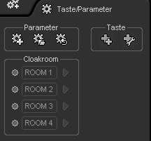 "Taste/parameter" sub-control gives you the functions, "Add new taste", "Customize taste", "Save parameter", "Load parameter", "Initialize parameter" and "Cloakroom" function.
There are some of GUI controls on the "parameter control" and "sub-control". This section shows you the common operations for them.
 [Slider control]
 [Edit control]
[Slider control]The Slider control is a standard GUI control of SILKYPIX®. It consists of a slider, an edit box and two spin buttons.
There are the following ways to change a value;
• Drag a slider pin to change a value
• Click a slider bar to set a value
• Click spin buttons to change a value
• Input a number on the edit box directly
• Double-clicking on the edit box to reset to default
There are the following ways to change a value;
• Drag a slider pin to change a value
• Click a slider bar to set a value
• Click spin buttons to change a value
• Input a number on the edit box directly
When you give a focus to the edit box, the background color of the edit box turns to red. It means you enter the "editing mode".
You can fix the value by pushing [ENTER] key or move a focus to other controls. Pushing [ESC] key aborts the "editing mode" and resumes the value.
This way may set an intermediate value that is not possible by another way.
• Changing a value with the mouse wheelYou can fix the value by pushing [ENTER] key or move a focus to other controls. Pushing [ESC] key aborts the "editing mode" and resumes the value.
This way may set an intermediate value that is not possible by another way.
The mouse wheel is valid when the mouse cursor is on the area of the "slider control".
The mouse wheel operation does not depend on the focus status of the windows control.
• Click the default mark on the slider bar to reset to defaultThe mouse wheel operation does not depend on the focus status of the windows control.
• Double-clicking on the edit box to reset to default
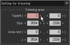
[Edit control]Edit control is one of a standard GUI control of SILKYPIX®, and it consists of an edit box and two spin buttons. For example, it is used on the "trimming setting" dialog.
• Click the spin buttons to change a value
• Input a number in the edit box directly
• Click the spin buttons to change a value
• Input a number in the edit box directly
When you give a focus to the edit box, the background color of the edit box turns to red. It means you enter the "editing mode".
You can fix the value by pushing [ENTER] key or move a focus to other controls. Pushing [ESC] key aborts the "editing mode" and resumes the value.
This way may set an intermediate value that is impossible by another way.
• Changing a value with the mouse wheelYou can fix the value by pushing [ENTER] key or move a focus to other controls. Pushing [ESC] key aborts the "editing mode" and resumes the value.
This way may set an intermediate value that is impossible by another way.
The mouse wheel is valid when the mouse cursor is on the area of the "slider control".
The mouse wheel operation does not depend on the focus status of the windows control.
• Double-clicking on the edit box to reset to defaultThe mouse wheel operation does not depend on the focus status of the windows control.
4.2 Sub-control
"Sub-control" is prepared for each parameter category, and they are classified as the following types;
(E) Taste/parameter
(A) Exposure bias
(B) Exposure bias fine tune
(A) White balance
(B) White balance adjustment
(A) Tone
(B) Tone curve
(A) Color (saturation/color mode)
(a) Sharpness
(a) Noise reduction
(B) Highlight controller
(B) Lens aberration controller
(B) Rotation/digital shift
(B) Fine color controller
(A) Development (demosaic sharp/resolution plus/colorspace)
(C) Trimming
(D) Histogram
(D) Exif information
There is one exception, (a)Sharpness and (a)Noise reduction has each sub-control, but they belong to the same parameter category and have a common taste.
Group (A) and (a) have a dropdown list on the "parameter control", and its sub-control is assigned to the display on the "tab page" as default.
Group (B) is for fine adjustment and its sub-control is assigned to a floating windows in hidden status as default. The Group (B) can be switched between Show and Hide status with the menu command [View(V)] or icons located atthe bottom of the "parameter control".
Group (C) is only displayed on the "Setting for trimming" dialog in the "trimming mode" .
Group (D) is not a GUI but an information window. You can switch the Group (D) between Show and Hide status with the menu command [View(V)] or icons located at the bottom of the "parameter control".
Group (E) is only displayed on the "Taste/parameter" sub-control, which is located on the "tab page" as default.
4.3 Exposure Bias
 You can adjust "Exposure bias" which determines a development gain at development process. This process is equivalent to the push-process or pull-process in film development.
This function allows you to get almost the same result as using the exposure compensation function of a camera.
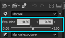
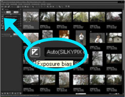
You can adjust a value with the "Exposure bias" slider or select the value from the "Exposure bias" dropdown list.
You can take a photograph on the condition that you can adjust exposure bias at development process later. Please refer to '10.1.2 Utilizing Difference between Exposure Biases of Camera and SILKYPIX®' for more details.
4.3.1 Auto Exposure Bias
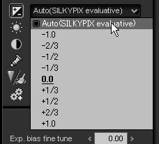 You can use "auto exposure bias" function by selecting "Auto(SILKYPIX evaluation)" from the "Exposure bias" dropdown list.
The algorithm of "auto exposure bias" function in SILKYPIX® detects an object, and analyzes included colors precisely.
And it allows the maximum level of color expressions on a display device or for a printing device, while reducing over-saturation or saturated color with the highly advanced image processing based on our excellent technologies.
This feature reduces time to adjust development parameters, and helps to create a picture with under exposure, which is peculiar to RAW data. It is effective when photographing with the underexposure method which only RAW can make it possible.
 You can make fine-tuning of exposure bias with the "Exp. bias fine tune" slider in the "Exposure" sub-control.
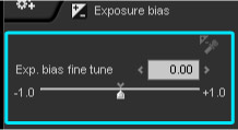 We recommend you to make rough adjustment with the "Exposure bias" dropdown list or "Exp. bias" slider, then to adjust exposure finely with "Exp. bias fine tune" slider.
 Since this parameter is independent of the "exposure bias" parameter, you can make exposure compensation for the "auto exposure" when you select "Auto(SILKYPIX evaluation)" as the "exposure bias" parameter.
For example, when you select "Auto(SILKYPIX evaluation)" as the "exposure bias" parameter and set this parameter +0.5EV, you can get +0.5EV brighter result than auto exposure.
This is the same as you use "exposure compensation" at the setting of "auto exposure" on your camera.
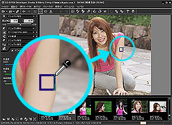
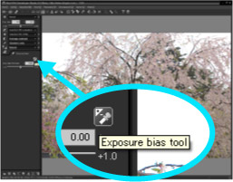 "Exposure bias tool" allows you to adjust the brightness of a specified point to a certain exposure level.
Click the "exposure bias tool" button on the "Exposure" sub-control or on the toolbar
 , then the operation mode is changed to the "exposure bias tool" mode.
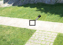 When you click a point or drag a rectangular selection on the preview image in the "exposure bias tool" mode, this feature sets an "exposure bias" such that brightness of the point or rectangular area becomes the "certain level".
The "certain level" is specified as the photosensitive level on the RAW data. You can change it in the "Function setting" dialog. Please refer to '9.3.1.2 Setting up Exposure Bias Tool' for more details.
This function works effectively even when a specified point is not achromatic color. In that case, the largest value of R, G, or B is selected as a target value and set to the "certain level".
For example, when you click the red area, this feature sets an \nohit"exposure bias" such that the R value becomes the "certain level".}
* About eyedropper operation, please refer to '9.3.2.2 Enable Continuous Operation of Eyedropper Tool'.
4.4 White Balance
"White balance" is the function to adjust white color.
Human eyes are adaptable to ambient light. We can perceive the white color of an object as white under the sunlight, lamps, and also fluorescent lamps. In photos, however, while "white" under the sunlight can be expressed as white, white under the lamp is expressed as reddish white, and under the fluorescent lamp, expressed as greenish or bluish white. What compensates these color changes is "white balance".
White balance adjustment vastly changes colors in photo and its impression. A white object in the photo can be expressed most beautifully and naturally with this function. In other words, the basic concept of white balance is expressing white as white.
However, it is not always true for all types of scenes.
For example, if a white object in evening glow is expressed completely in white, you will not be able to know that it is a sunset scene. If you want to produce a melancholy mood on your picture in the clouded sky, it may be required to change to more bluish colors.
Although most cameras today can automatically adjust the white balance, it is not always correct, and even if it is correct, the result is not always what you really want. Therefore, it becomes necessary to adjust the white balance according to each expression.
However, it is very difficult to select and correct the white balance while you are taking a picture.
If you take a picture with RAW data, you can change the white balance as you want when you are developing a photo and select an appropriate expression for each scene. It is not so exaggerating to say that the greatest advantage of using the RAW data picture is this function.
4.4.1 Adjusting White Balance with Taste
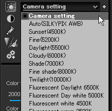 This is the way to make adjustment by selecting the white balance adjusted for each light source in advance. Select a taste that specifies a light source in the dropdown list of "white balance".
You can also change settings in detail later, so it is convenient to select the light source first.
The preset items displayed in the dropdown list differ in each type of camera.
There are "taste" that are prepared in the dropdown list of "white balance", which specify each light source.
4.4.2 Auto White Balance
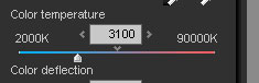
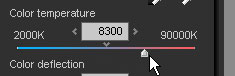
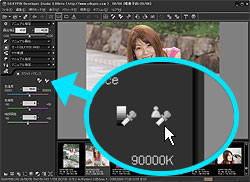
 This is the way to adjust the white balance by specifying the color temperature.
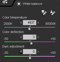
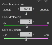
There is a "color temperature" adjustment slider on the "White balance" sub-control.
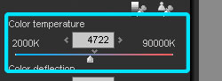 Move this slider to find the point where colors of the object are well balanced.
When the color of the object is reddish or yellowish, move the slider to decrease the color temperature.
When the color of the object is bluish, move the slider to increase the color temperature.
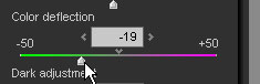
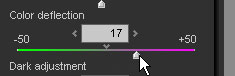
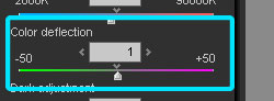 The "Color deflection" slider is used to remove color casts. Before using it, adjust the color temperature first.
When the color of the object appears greenish, move the slider to the + side.
When the color of the object appears magentish, move the slider to the - side.
* Refer to '10.4.1 Color Temperature and Color Deflection' for your information.
4.4.4 Gray Balance Tool
 When clicking the "Gray balance tool" on the "White balance" sub-control or toolbar
  , you can enter the "gray balance tool" mode.
Then, click or drag the area that you want to change gray to specify the range. The white balance will be set to express that area in gray.
When there is a gray object in a photo, you can easily adjust the white balance with this function.
Taking a photograph of a gray chart or white paper in advance may become very helpful.
* For eyedropper operation, refer to '9.3.2.2 Enable Continuous Operation of Eyedropper Tool'.
4.4.5 Dark Adjustment
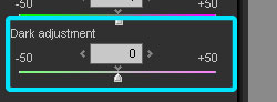 While "color temperature" and "color deflection" change the white balance of the entire image, the "dark adjustment" amends color casts of the dark portion of the image.
Green or magenta color casts sometimes occurs in the dark portion although the white balance of the bright portion in a scene is well.
In this case, you can amend color casts with this function, and you can continuously remove color fluctuation from the dark portion to the bright portion.
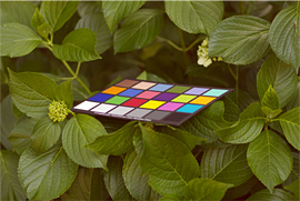
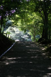
For example, the left picture shows a sample of strong magenta casts in the dark portion.
When looking a gray patch of Macbeth chart, you will find that the bright patch is well white balanced, but the color of the dark portion becomes magenta. This affects the color of leaves (becoming yellow) and shadow (becoming red).
This function drastically eases the problem which a white balance of only dark portion is shifted. The right picture shows what happened on the same picture when magenta casts is removed by the dark adjustment function.
[Detail of color casts in the dark area]
The main purpose of the function is to remove color casts in the dark area, however, with this function, you can also change the white balance of the dark area and bright area.
The left picture shows the original of photography. The center shows the picture of which white balance is set as the "Fine" according to the area in the direct sunlight at the back in the photo. As you see, the color of the ground affected by the sun fleck becomes almost greenish. When changing the white balance of the ground in order to correct the color, the color of the area in the sunlight becomes magentish in turn. Therefore, only with the white balance you can't get the perfect effect for both of the ground and the area in the sunlight simultaneously. Actually, the color of the ground should be green because sun fleck is surely reflected to the ground, and the center picture shows the actual impression at photographing. However, human eyes adjust colors to match to what they want to see, so impression of the picture should be adjusted based on that. In such case, you should change the white balance of the dark area by using the dark adjustment actively. The right picture shows how the dark adjustment removes the green casts of the ground without changing much of the color of the bright area in the sunlight. As you see, the impression has been improved.
Human eyes are adaptable to ambient light. We can perceive the white color of an object as white under the sunlight, lamps, and also fluorescent lamps. In photos, however, while "white" under the sunlight can be expressed as white, white under the lamp is expressed as reddish white, and under the fluorescent lamp, expressed as greenish or bluish white. What compensates these color changes is "white balance".
White balance adjustment vastly changes colors in photo and its impression. A white object in the photo can be expressed most beautifully and naturally with this function. In other words, the basic concept of white balance is expressing white as white.
However, it is not always true for all types of scenes.
For example, if a white object in evening glow is expressed completely in white, you will not be able to know that it is a sunset scene. If you want to produce a melancholy mood on your picture in the clouded sky, it may be required to change to more bluish colors.
Although most cameras today can automatically adjust the white balance, it is not always correct, and even if it is correct, the result is not always what you really want. Therefore, it becomes necessary to adjust the white balance according to each expression.
However, it is very difficult to select and correct the white balance while you are taking a picture.
If you take a picture with RAW data, you can change the white balance as you want when you are developing a photo and select an appropriate expression for each scene. It is not so exaggerating to say that the greatest advantage of using the RAW data picture is this function.
4.4.1 Adjusting White Balance with Taste
This is the way to make adjustment by selecting the white balance adjusted for each light source in advance. Select a taste that specifies a light source in the dropdown list of "white balance".You can also change settings in detail later, so it is convenient to select the light source first.
The preset items displayed in the dropdown list differ in each type of camera.
There are "taste" that are prepared in the dropdown list of "white balance", which specify each light source.
| Auto | ... | This auto white balance is based on a unique algorithm, which is completely different from the auto white balance function on cameras. The feature of this algorithm is that it can detect color of the light sources very accurately. |
| Daylight | ... | White balance suitable for shooting outdoors |
| Sunset | ... | White balance suitable for shooting in the direct sunlight of the evening glow |
| Fine | ... | White balance suitable for shooting in the direct sunlight of daytime in fine weather |
| Daylight | ... | White balance suitable for shooting in the direct sunlight in fine daytime (including obscured sky) |
| Cloudy | ... | White balance suitable for shooting in scattered light from clouds in overcast day |
| Shade | ... | White balance suitable for shooting objects in the shade in fine daytime (including obscured sky) |
| Fine shade | ... | White balance suitable for shooting objects in the shade in clean and sunny daytime |
| Fluorescent | ... | White balance suitable for shooting objects under fluorescent light |
| Three-band fluorescent | ... | White balance suitable shooting objects under three-band fluorescent light widely used in home |
| Tungsten | ... | White balance suitable for shooting objects under incandescent lamp |
| Flash | ... | White balance suitable for shooting objects in the photoflash |
This function adjusts the white balance automatically. As previously mentioned, there is no right answer for the white balance. Because it depends on what the photographer (you) want to express.
However, it is a hard job to select appropriate white balance for each photo, when you have to develop a lot of pictures.
Don't worry. You can use the "auto white balance" function, which expresses a light source color in white automatically.
The method and logic of "auto white balance" of SILKYPIX® is fundamentally different from "auto white balance" in cameras. And it allows very accurate detection of the white balance of high color saturation or an object having no white area, which typical "auto white balance" function cannot handle well.
This "auto white balance" function will automatically adjust and reproduce the portion to white, which was white at the time when the photograph was taken.
Since it is the fundamental method of the white balance that it adjusts and reproduces the white object to white, you can adjust "white balance" quickly by using the "auto white balance" function at first.
Then please adjust "white balance" manually only if the result of the "auto white balance" is not correct or is not suitable for your thought.
4.4.3 Color Temperature and Color DeflectionHowever, it is a hard job to select appropriate white balance for each photo, when you have to develop a lot of pictures.
Don't worry. You can use the "auto white balance" function, which expresses a light source color in white automatically.
The method and logic of "auto white balance" of SILKYPIX® is fundamentally different from "auto white balance" in cameras. And it allows very accurate detection of the white balance of high color saturation or an object having no white area, which typical "auto white balance" function cannot handle well.
This "auto white balance" function will automatically adjust and reproduce the portion to white, which was white at the time when the photograph was taken.
Since it is the fundamental method of the white balance that it adjusts and reproduces the white object to white, you can adjust "white balance" quickly by using the "auto white balance" function at first.
Then please adjust "white balance" manually only if the result of the "auto white balance" is not correct or is not suitable for your thought.
This is the way to adjust the white balance by specifying the color temperature. There is a "color temperature" adjustment slider on the "White balance" sub-control.
Move this slider to find the point where colors of the object are well balanced. When the color of the object is reddish or yellowish, move the slider to decrease the color temperature.
When the color of the object is bluish, move the slider to increase the color temperature.
The "Color deflection" slider is used to remove color casts. Before using it, adjust the color temperature first.When the color of the object appears greenish, move the slider to the + side.
When the color of the object appears magentish, move the slider to the - side.
* Refer to '10.4.1 Color Temperature and Color Deflection' for your information.
When clicking the "Gray balance tool" on the "White balance" sub-control or toolbar , you can enter the "gray balance tool" mode.Then, click or drag the area that you want to change gray to specify the range. The white balance will be set to express that area in gray.
When there is a gray object in a photo, you can easily adjust the white balance with this function.
Taking a photograph of a gray chart or white paper in advance may become very helpful.
* For eyedropper operation, refer to '9.3.2.2 Enable Continuous Operation of Eyedropper Tool'.
While "color temperature" and "color deflection" change the white balance of the entire image, the "dark adjustment" amends color casts of the dark portion of the image.Green or magenta color casts sometimes occurs in the dark portion although the white balance of the bright portion in a scene is well.
In this case, you can amend color casts with this function, and you can continuously remove color fluctuation from the dark portion to the bright portion.
For example, the left picture shows a sample of strong magenta casts in the dark portion.
When looking a gray patch of Macbeth chart, you will find that the bright patch is well white balanced, but the color of the dark portion becomes magenta. This affects the color of leaves (becoming yellow) and shadow (becoming red).
This function drastically eases the problem which a white balance of only dark portion is shifted. The right picture shows what happened on the same picture when magenta casts is removed by the dark adjustment function.
[Detail of color casts in the dark area]
 No Correction | 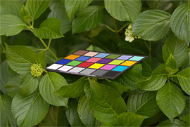 Dark Adjustment (Value: -5) |
The main purpose of the function is to remove color casts in the dark area, however, with this function, you can also change the white balance of the dark area and bright area.
The left picture shows the original of photography. The center shows the picture of which white balance is set as the "Fine" according to the area in the direct sunlight at the back in the photo. As you see, the color of the ground affected by the sun fleck becomes almost greenish. When changing the white balance of the ground in order to correct the color, the color of the area in the sunlight becomes magentish in turn. Therefore, only with the white balance you can't get the perfect effect for both of the ground and the area in the sunlight simultaneously. Actually, the color of the ground should be green because sun fleck is surely reflected to the ground, and the center picture shows the actual impression at photographing. However, human eyes adjust colors to match to what they want to see, so impression of the picture should be adjusted based on that. In such case, you should change the white balance of the dark area by using the dark adjustment actively. The right picture shows how the dark adjustment removes the green casts of the ground without changing much of the color of the bright area in the sunlight. As you see, the impression has been improved.
 No Correction | 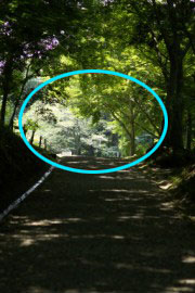 White Balance (Fine:5200K) | 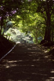 White Balance (Fine:5200K), Dark Adjustment (+6) |
[Using with "color temperature" and "color deflection"]
When changing the white balance, first decide the white balance of the bright portion by "color temperature" and "color deflection". Then, adjust the dark portion where you want to remove color casts with the "dark adjustment" function. This function works effectively on the dark portion, but also affects slightly on the color of the bright portion. Therefore, we recommend you to adjust the "color deflection" again to finish the job.
[Detail of color casts in the dark area]
Why does color casts occur in the dark portion?
Leakage current of an image sensor causes it. Because of the leakage current, the intense black is not recorded as 0 in RAW data. SILKYPIX® is subtracting such leakage current data from RAW data (optical black correction) to develop an image.
However, a higher temperature makes the larger leakage current of an image sensor, and vice versa. In most cases, a camera records black with constant level, regardless of the temperature, but some conditions or photographing environment may affect the level (optical black level). According to the color sensitivity of each image sensor, as the optical black level becomes larger, the color of the dark area becomes magentish, and as the level becomes smaller, the color becomes greenish. The "dark adjustment" function reduces coloring of the dark portion in those cases. It also corrects the white balance of the dark portion when a photograph is taken under severe conditions such as extremely low temperature, high-sensitive photography, and long exposure.
4.4.6 White Balance AdjustmentWhen changing the white balance, first decide the white balance of the bright portion by "color temperature" and "color deflection". Then, adjust the dark portion where you want to remove color casts with the "dark adjustment" function. This function works effectively on the dark portion, but also affects slightly on the color of the bright portion. Therefore, we recommend you to adjust the "color deflection" again to finish the job.
[Detail of color casts in the dark area]
Why does color casts occur in the dark portion?
Leakage current of an image sensor causes it. Because of the leakage current, the intense black is not recorded as 0 in RAW data. SILKYPIX® is subtracting such leakage current data from RAW data (optical black correction) to develop an image.
However, a higher temperature makes the larger leakage current of an image sensor, and vice versa. In most cases, a camera records black with constant level, regardless of the temperature, but some conditions or photographing environment may affect the level (optical black level). According to the color sensitivity of each image sensor, as the optical black level becomes larger, the color of the dark area becomes magentish, and as the level becomes smaller, the color becomes greenish. The "dark adjustment" function reduces coloring of the dark portion in those cases. It also corrects the white balance of the dark portion when a photograph is taken under severe conditions such as extremely low temperature, high-sensitive photography, and long exposure.
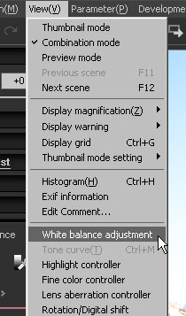 The menu command [View(V)]-[White balance adjustment] displays the "White balance adjustment" sub-control.
Use this function when you want to adjust a little of the white balance at the last sequence.
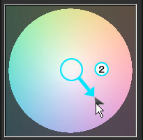
You can adjust white balance in detail with this sub-control, which has a "white balance target" graphic control, a "saturation" slider, and a "hue" slider.
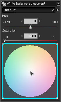 • White balance target
This graphic control is based on the accurate colorspace. You can set the white balance viscerally by clicking a mouse directly.
[Mouse wheel operation]
[Mouse wheel operation]
You can change "saturation" parameter with the mouse wheel on the white balance target.
And with [SHIFT] key, you can change "hue" parameter.
And with [SHIFT] key, you can change "hue" parameter.
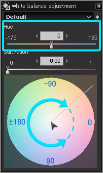 • "Hue" slider
It shows the angle from the right hand side of the white balance target in clockwise. Move the slider to change the angle in detail.
You can specify the setting value indicates:
You can specify the setting value indicates:
| 0 | right from the center |
| 90 | downward from the center |
| 180(-180) | left from the center |
| -90 | upward from the center |
| + | lower half from the center |
| - | upper half from the center |
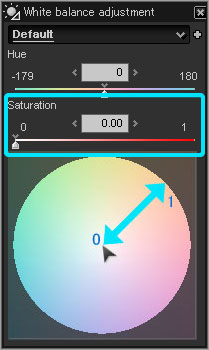 • "Saturation" slider
It shows the radius from the center of the white balance target. Move the slider to change the radius in detail. The range is 0.00 to 1.00 (0.00 is the center of the white balance target, 1.00 is the maximum radius).
We will introduce you some setting samples to show how to set to get colors you want.
 1) To remove reddish color (red casts)
 2) To remove bluish color (blue casts)
 3) To remove purplish color (magenta casts)
 4) To remove greenish color
1) To remove reddish color (red casts)(1) Move the "Color temperature" slider to the smaller (lower) side.
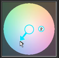 (2) With the white balance target in the "White balance adjustment" sub-control, move the cursor to the opposite (blue) direction.
(2) With the white balance target in the "White balance adjustment" sub-control, move the cursor to the opposite (blue) direction.2) To remove bluish color (blue casts)(1) Move the "Color temperature" slider to the larger (higher) side.
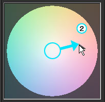 (2) With the white balance target in the "White balance adjustment" sub-control, move the cursor to the opposite (red) direction.
(2) With the white balance target in the "White balance adjustment" sub-control, move the cursor to the opposite (red) direction. 3) To remove purplish color (magenta casts)(1) Move the "Color deflection" slider to the - side.
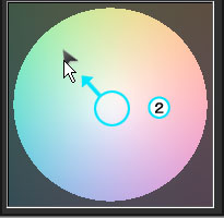 (2) With the white balance target in the "White balance adjustment" sub-control, move the cursor to the opposite (green) direction.
(2) With the white balance target in the "White balance adjustment" sub-control, move the cursor to the opposite (green) direction. 4) To remove greenish color(1) Move the "Color deflection" slider to the + side.
 (2) With the white balance target in the "White balance adjustment" sub-control, move the cursor to the opposite (purple) direction.
(2) With the white balance target in the "White balance adjustment" sub-control, move the cursor to the opposite (purple) direction. 4.5 Tone Adjustment
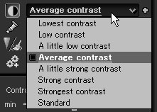
Tone adjustment parameter adjusts the contrast, high or low.
4.5.1 Adjusting Tone with Taste
4.5.2 Fine-Tuning Tone
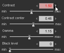
 Tone adjustment can be changed with "Contrast", "Contrast center, and "Gamma."
By preset, these parameters are fixed based on the condition at photographing of average object with appropriate exposure (or with correct adjustment by the exposure bias), but you can also set them manually to make more precise adjustments.
Switching to the "Tone" sub-control, three sliders appear. The details of parameters are shown below.
(1) Contrast
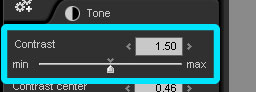 Contrast means the difference between bright area and dark area.
When increasing the contrast, the bright area becomes brighter and the dark area becomes darker, i.e. high contrast.
On the contrary, when decreasing the contrast, difference between the bright area and dark area becomes smaller, i.e. low contrast.
(2) Contrast center
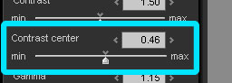 This is the reference to judge the brightness when adjusting the contrast. Upper from the contrast center is considered as bright, and lower is considered as dark. In other words, this reference decides the point where the brightness level is not changed when adjusting the contrast.
When setting the contrast center smaller, you feel the tone of an image becomes lighter.
This is because the contrast is increased based on the dark area, and causes the dark area to turn smaller and the bright area larger.
On the contrary, when setting the contrast center bigger, you feel that the tone of the image becomes darker.
Increasing the contrast means compressing the gray scale of bright area and dark area and expanding the gray scale around the contrast center.
Therefore, if a target object is dark, set the contrast center smaller, and if it is bright, set the contrast center bigger to get the ideal tone.
The contrast center is displayed on the "Histogram." When you move the cursor to the position on the photo currently displayed in the preview screen while histogram is displayed, the brightness of R, G, and B on that point is displayed. With this function, make adjustments, looking the brightness distribution on the area you want to add contrast, and you can find the appropriate level relatively easily.
(3) Gamma
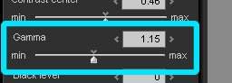 Gamma is brightness adjustment. As the gamma is larger, the overall brightness becomes higher, and vice versa.
You may think it is the same as exposure bias operation, however, they are not the same thing.
With the exposure bias, the brightness is adjusted without changing the ratio of bright range and dark range . On the contrary, with gamma, the ratio is changed.
When increasing the gamma value, the bright range is compressed, and the dark range is expanded.
When decreasing the gamma value, the dark range is compressed and the bright range is expanded.
Therefore, in this software, this operation is considered as tone-change-operation and classified as 'Tone Adjustment' since it changes tone.
As just described, operation to increase the contrast compresses both bright range and dark range and expands the area with the intermediate range of brightness.
This means an object with the intermediate range of brightness is expressed in the much of a gap between brightness and darkness.
"Contrast center" fixes the intermediate range of brightness.
(4) Black level
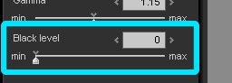 Black level controls create clear expression of the dark area.
You can specify the level of black with this function. When increasing this parameter, the color black becomes deeper black.
This function works effectively when a picture is taken against the sun and the image becomes unimpressive, or when a landscape image becomes obscured, influenced by light scattering in air.
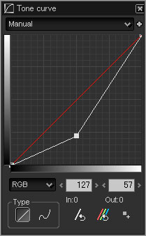
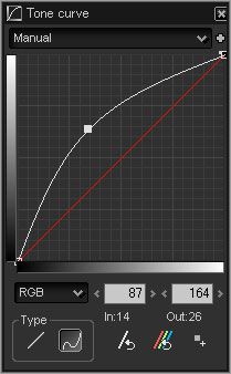
4.5.3 Tone Curve
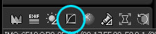
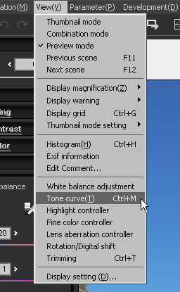 The menu command [View(V)]-[Tone curve(T)] displays the "Tone curve" sub-control.
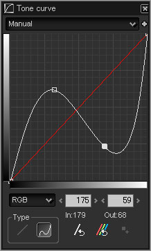 You can set the curve which changes lightness while editing a picture. The horizontal axis means input (brightness of source picture) and the vertical axis means output (brightness of result picture after transfoming). You can control lightness in a picture by operating this curve.
* By dragging window's frame of the "Tone curve" sub-control, you can adjust a size of the dialog.
In addition, by dragging it while pressing the Shift key, you can adjust the size while fixing aspect ratio of it.
4.5.3.1 Editing Points
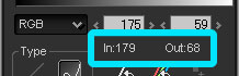 The curve is drawn as passing through a point, and you can operate the curve by moving the point. During the operation, coordinates are displayed at the right side of the "Init all" button. Guide display function: When there is a cursor on the preview, a value of the position is displayed.
(1) Adding Point
4.5.3.2 Tone Curve: Button
(1) Type Combo Box You can select the value which you want to operate a gradation process in a dropdown list.
The process is reflected in order of tone curve settings for each R, G, and B first and then tone curve setting for RGB.
(2) "Init" button ... Initializes the lightness setting.
(3) "Init all" button ... Initializes the all tone curve settings of RGB, R, G, and B.
(4) Guide display ... Displays a value of position where a cursor is on.
(5) "Add point" button ... Adds a point on the presently selected type of tone curve by moving the eyedropper icon on the preview and clicking the point to edit (By clicking the point while pressing the Ctrl key, you can add a point on all tone curves of RGB, R, G, and B).
* '(4) Guide display' and '(5)"Add point" button' are valid only when all points are monotone increasing or monotone decreasing.
[How to use "Add point" function]
4.5.3.3 Type
4.5.1 Adjusting Tone with Taste
4.5.2 Fine-Tuning Tone
 Select a Tone adjustment can be changed with "Contrast", "Contrast center, and "Gamma."
By preset, these parameters are fixed based on the condition at photographing of average object with appropriate exposure (or with correct adjustment by the exposure bias), but you can also set them manually to make more precise adjustments.
Switching to the "Tone" sub-control, three sliders appear. The details of parameters are shown below.
(1) Contrast
Contrast means the difference between bright area and dark area.When increasing the contrast, the bright area becomes brighter and the dark area becomes darker, i.e. high contrast.
On the contrary, when decreasing the contrast, difference between the bright area and dark area becomes smaller, i.e. low contrast.
This is the reference to judge the brightness when adjusting the contrast. Upper from the contrast center is considered as bright, and lower is considered as dark. In other words, this reference decides the point where the brightness level is not changed when adjusting the contrast.When setting the contrast center smaller, you feel the tone of an image becomes lighter.
This is because the contrast is increased based on the dark area, and causes the dark area to turn smaller and the bright area larger.
On the contrary, when setting the contrast center bigger, you feel that the tone of the image becomes darker.
Increasing the contrast means compressing the gray scale of bright area and dark area and expanding the gray scale around the contrast center.
Therefore, if a target object is dark, set the contrast center smaller, and if it is bright, set the contrast center bigger to get the ideal tone.
The contrast center is displayed on the "Histogram." When you move the cursor to the position on the photo currently displayed in the preview screen while histogram is displayed, the brightness of R, G, and B on that point is displayed. With this function, make adjustments, looking the brightness distribution on the area you want to add contrast, and you can find the appropriate level relatively easily.
Gamma is brightness adjustment. As the gamma is larger, the overall brightness becomes higher, and vice versa.You may think it is the same as exposure bias operation, however, they are not the same thing.
With the exposure bias, the brightness is adjusted without changing the ratio of bright range and dark range . On the contrary, with gamma, the ratio is changed.
When increasing the gamma value, the bright range is compressed, and the dark range is expanded.
When decreasing the gamma value, the dark range is compressed and the bright range is expanded.
Therefore, in this software, this operation is considered as tone-change-operation and classified as 'Tone Adjustment' since it changes tone.
As just described, operation to increase the contrast compresses both bright range and dark range and expands the area with the intermediate range of brightness.
This means an object with the intermediate range of brightness is expressed in the much of a gap between brightness and darkness.
"Contrast center" fixes the intermediate range of brightness.
Black level controls create clear expression of the dark area.You can specify the level of black with this function. When increasing this parameter, the color black becomes deeper black.
This function works effectively when a picture is taken against the sun and the image becomes unimpressive, or when a landscape image becomes obscured, influenced by light scattering in air.
The menu command [View(V)]-[Tone curve(T)] displays the "Tone curve" sub-control.You can set the curve which changes lightness while editing a picture. The horizontal axis means input (brightness of source picture) and the vertical axis means output (brightness of result picture after transfoming). You can control lightness in a picture by operating this curve.* By dragging window's frame of the "Tone curve" sub-control, you can adjust a size of the dialog.
In addition, by dragging it while pressing the Shift key, you can adjust the size while fixing aspect ratio of it.
4.5.3.1 Editing Points
The curve is drawn as passing through a point, and you can operate the curve by moving the point. During the operation, coordinates are displayed at the right side of the "Init all" button. Guide display function: When there is a cursor on the preview, a value of the position is displayed.(1) Adding Point
Click the mouse on a graph to place a point at the position.
(2) Moving PointMove the mouse cursor around the point that already exist, then cursor image changes to the {crosshair cursor}.
Drag the mouse in this state to move the existing point.
(3) Deleting PointDrag the mouse in this state to move the existing point.
Move and right-click the mouse on the target point to delete.
In addition, you can delete the current point by pressing the Delete key. You can delete up to the last two points.
(4) Current PointIn addition, you can delete the current point by pressing the Delete key. You can delete up to the last two points.
The point displayed as a white rectangle is the current point, which is the last point you operated.
By pressing the Delete key, you can delete this current point.
By pressing the Delete key, you can delete this current point.
(1) Type Combo Box You can select the value which you want to operate a gradation process in a dropdown list.
| RGB | Set gradation process for all RGB values with the tone curve. |
| R | Set gradation process for R value with the tone curve. |
| G | Set gradation process for G value with the tone curve. |
| B | Set gradation process for B value with the tone curve. |
The process is reflected in order of tone curve settings for each R, G, and B first and then tone curve setting for RGB.
(3) "Init all" button ... Initializes the all tone curve settings of RGB, R, G, and B.
(4) Guide display ... Displays a value of position where a cursor is on.
(5) "Add point" button ... Adds a point on the presently selected type of tone curve by moving the eyedropper icon on the preview and clicking the point to edit (By clicking the point while pressing the Ctrl key, you can add a point on all tone curves of RGB, R, G, and B).
* '(4) Guide display' and '(5)"Add point" button' are valid only when all points are monotone increasing or monotone decreasing.
[How to use "Add point" function]
Click "Add point" button to add the target tone point on the tone curve.
(1) Select the target scene on the preview window.
(2) Execute menu command [View(V)]-[\nohittone curve}(T)], then the "\nohittone curve}" sub-control is displayed.
(3) Click "Add point" button to switch operation mode to "Add point for tone curve".
(4) Click the target point on the preview scene.
(5) Then the target point is added on the tone curve.
* In this time, with [CTRL] key for windows and [Command]key for Macintosh, the target point is added on each tone curve (RGB, R, G, B).
(6) You can adjust tone curve by moving the target point that is added in this operation.
(7) Then the tone curve that you adjusted is applied to the target scene.
Regarding "Tone curve", you can select the following two types.
 (1) "Straight" Connects placed points with a line segment.
 (2) "Curve" Connects placed points with the smooth curve which passing through the points.
(1) "Straight" Connects placed points with a line segment.(2) "Curve" Connects placed points with the smooth curve which passing through the points.4.6 Color Adjustment
You can select and adjust saturation and color mode.
4.6.1 Adjusting Saturation with Taste
 Select a taste from the dropdown list of "Color".
Select "Monochrome" or "Monochrome 2" to create a monochrome picture.
Monochrome 2 can create a natural-looking monochrome picture that has more similar sensitivity characteristics to human eyes than Monochrome.
Select the appropriate mode for your picture according to the scene.
Use the final color image at the last sequence to create a monochrome picture.
You will be able to create various monochrome pictures by changing the white balance and color mode.
4.6.2 Fine-Tuning Saturation
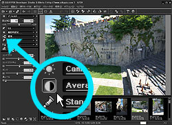
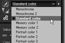
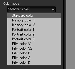 The color mode sets orientation of color reproduction. Select a mode in the "color mode" dropdown list in the "Color" sub-control.
There are "Standard color", "Memory color", "Portrait color", and "Film color" in the color mode.
4.6.3.1 Standard Color
 You can switch operation mode to "Skin color tool" with the "skin color tool" button on the "white balance" sub-control, or menu command [Operation(M)]-[Skin color tool].
In the "skin color tool" mode, you can click or drag a rectangle area at the target skin on the preview, then the target area is automatically adjusted to beautiful skin color and also exposure bias is adjusted.
 If the result is too red, green, or blue, please click that area again. By a few repeatable operations, you can find out the suitable skin color.
Then you can additionally adjust "White balance adjustment", "Exp. bias fine tune", or "Tone" for fine-tuning.
If you use this tool on the woman's face, please avoid the emphasized make-up area. Basic foundation area, especially dull color area is suitable for picking up,
* For continuous operation, please refer to '9.3.2.2 Enable Continuous Operation of Eyedropper Tool'.
4.6.1 Adjusting Saturation with Taste
Select a taste from the dropdown list of "Color".Select "Monochrome" or "Monochrome 2" to create a monochrome picture.
Monochrome 2 can create a natural-looking monochrome picture that has more similar sensitivity characteristics to human eyes than Monochrome.
Select the appropriate mode for your picture according to the scene.
Use the final color image at the last sequence to create a monochrome picture.
You will be able to create various monochrome pictures by changing the white balance and color mode.
The taste includes the range of saturation that is considered to be used normally. However, if you want more or less saturation, or adjust saturation more precisely, you can set manually.
In the taste dropdown list, switch to the manual setting first and then make adjustments in detail with the slider in the "Color" sub-control.
4.6.3 Selecting Color ModeIn the taste dropdown list, switch to the manual setting first and then make adjustments in detail with the slider in the "Color" sub-control.
The color mode sets orientation of color reproduction. Select a mode in the "color mode" dropdown list in the "Color" sub-control.There are "Standard color", "Memory color", "Portrait color", and "Film color" in the color mode.
4.6.3.1 Standard Color
This is the standard color creation of SILKYPIX®, which is aiming at true color reproduction.
This mode provides reasonable natural colors for many scenes.
4.6.3.2 Memory ColorThis mode provides reasonable natural colors for many scenes.
True colors in photo are not always "beautiful colors."
It is common knowledge that colors in our memory, or colors of an object that we want are different from actual colors. Although they differ in individuals, we can find a constant trend and directional character.
We consider the picture "beautiful" when colors in our memory or colors we want to see are printed in the photo.
This mode creates colors of such memory color or colors ordinary people want to see.
Although the directional character is different for each color, in short, saturation tends to be high, and the saturation level is higher than the "Standard color" mode.
This mode provides "beautiful color photo" for many scenes, but colors of some objects with high saturation such as flowers become too vivid and changed wrongly.
In such case, adjust with '4.10 Fine Color Controller', set lower saturation level or lower development gain to correct the color.
Memory color 1 performs the same color reproduction as "memory color 1" in the previous version of the software. Memory color 2 provides human-oriented touch of memory color with the new color reproduction technology "3-dimentional color mapping method."
Select the mode, as you like.
* When decreasing the development gain to express images darkly, it becomes easier to reproduce the color of object with high saturation. This is because most display devices (such as a display) and printing devices (such as a printer) are not good at outputting high saturation and brightness simultaneously.
This mode is not effective in a portrait photo.
The color of human skin is a type of orange and recorded with high saturation. Therefore, it is reproduced in high saturation with this mode, but every models or photographer does not want high saturation output for human skin.
If you want more beautiful skin color, select "Portrait color" in the color mode.
4.6.3.3 Portrait ColorIt is common knowledge that colors in our memory, or colors of an object that we want are different from actual colors. Although they differ in individuals, we can find a constant trend and directional character.
We consider the picture "beautiful" when colors in our memory or colors we want to see are printed in the photo.
This mode creates colors of such memory color or colors ordinary people want to see.
Although the directional character is different for each color, in short, saturation tends to be high, and the saturation level is higher than the "Standard color" mode.
This mode provides "beautiful color photo" for many scenes, but colors of some objects with high saturation such as flowers become too vivid and changed wrongly.
In such case, adjust with '4.10 Fine Color Controller', set lower saturation level or lower development gain to correct the color.
Memory color 1 performs the same color reproduction as "memory color 1" in the previous version of the software. Memory color 2 provides human-oriented touch of memory color with the new color reproduction technology "3-dimentional color mapping method."
Select the mode, as you like.
* When decreasing the development gain to express images darkly, it becomes easier to reproduce the color of object with high saturation. This is because most display devices (such as a display) and printing devices (such as a printer) are not good at outputting high saturation and brightness simultaneously.
This mode is not effective in a portrait photo.
The color of human skin is a type of orange and recorded with high saturation. Therefore, it is reproduced in high saturation with this mode, but every models or photographer does not want high saturation output for human skin.
If you want more beautiful skin color, select "Portrait color" in the color mode.
"Portrait color" is color reproduction, which is an emphasis on tone and is better suited for photographing a person.
When this mode is not appropriate for your picture, use the "Standard color."
Portrait color 2 is a mode that provides flesh color with the new color reproduction technology "3-dimentional color mapping method", which is different from Portrait color 1.
Portrait color 3 provides colors of clothes and background slightly shifted to "memory color" based on "Portrait color 2."
Use these color modes according to your preference.
4.6.3.4 Film ColorWhen this mode is not appropriate for your picture, use the "Standard color."
Portrait color 2 is a mode that provides flesh color with the new color reproduction technology "3-dimentional color mapping method", which is different from Portrait color 1.
Portrait color 3 provides colors of clothes and background slightly shifted to "memory color" based on "Portrait color 2."
Use these color modes according to your preference.
This mode provides color reproduction similar to reversal film.
In film, a light source or exposure impacts on colors, which is different from digital camera. If you want a nice color with film, the color of light source and exposure range are limited.
Since this limitation reduces the advantage of digital camera, we have adjusted each parameter to realize all adjustment functions including the white balance or exposure bias and film tone colors simultaneously.
Therefore, you can get the film-like color easily when you select this "Film color" in the "Color mode."
However, the tone of gray axis does not change only by changing this mode. Adjust the tone, too, if required.
Since the film tone mode (for example, vivid film tone V) makes saturation high, colors in that mode changes according to the white balance adjustment.
In the "White balance" sub-control, adjust the white balance to create your favorite colors if needed.
'4.10 Fine Color Controller' allows more precise color adjustment.
4.6.3.5 Skin Color ToolIn film, a light source or exposure impacts on colors, which is different from digital camera. If you want a nice color with film, the color of light source and exposure range are limited.
Since this limitation reduces the advantage of digital camera, we have adjusted each parameter to realize all adjustment functions including the white balance or exposure bias and film tone colors simultaneously.
Therefore, you can get the film-like color easily when you select this "Film color" in the "Color mode."
However, the tone of gray axis does not change only by changing this mode. Adjust the tone, too, if required.
Since the film tone mode (for example, vivid film tone V) makes saturation high, colors in that mode changes according to the white balance adjustment.
In the "White balance" sub-control, adjust the white balance to create your favorite colors if needed.
'4.10 Fine Color Controller' allows more precise color adjustment.
You can switch operation mode to "Skin color tool" with the "skin color tool" button on the "white balance" sub-control, or menu command [Operation(M)]-[Skin color tool].In the "skin color tool" mode, you can click or drag a rectangle area at the target skin on the preview, then the target area is automatically adjusted to beautiful skin color and also exposure bias is adjusted.
If the result is too red, green, or blue, please click that area again. By a few repeatable operations, you can find out the suitable skin color.Then you can additionally adjust "White balance adjustment", "Exp. bias fine tune", or "Tone" for fine-tuning.
If you use this tool on the woman's face, please avoid the emphasized make-up area. Basic foundation area, especially dull color area is suitable for picking up,
* For continuous operation, please refer to '9.3.2.2 Enable Continuous Operation of Eyedropper Tool'.
4.7 Sharpness/Noise Reduction
"Sharpness" and "Noise reduction" have each own sub-control, but they belong to the common category of development parameter.
Therefore they have common taste dropdown list. Please remember that the their taste item contains both sharpness and noise reduction parameter.
If you make sharpness stronger, then noise is also emphasized. Therefore you should adjust sharpness and noise reduction at the same time with balance.
4.7.1 Adjusting Sharpness with Taste
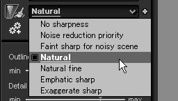 Select a taste from the dropdown list of "Sharpness/Noise reduction".
4.7.2 Sharpness Adjustment
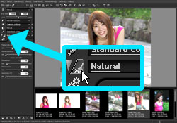 Noise means the rough texture that occurs in high sensitive photography. We call it high frequency noise in the software.
At the high sensitive photography, red, green, or blue spots appear, too. We call them color noise in this software.
The function to remove such noise is the noise reduction.
In this software, the noise reduction function has independent parameter for each category.
The following sections are summaries of the function of noise reduction.
4.7.3.1 False Color Control
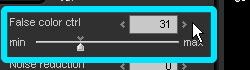 The false color control function changes the process level of false color reduction.
The software enables to reduce both false colors occur in the fine structure area (high frequency area) and color noise.
When too much color noise at high sensitive photography or false colors in the fine structure area occur, increases the reduction level.
However, there are some demerits in this function.
As the reduction level becomes stronger, the color separation level goes down, which makes colors in the color boundary blur. Also, there is a problem of "color spill," which is the phenomenon that occurs when the vivid color leaks around the picture.
Therefore, too strong reduction level may decrease the picture quality.
4.7.3.2 Noise Reduction
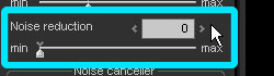 Use the "Noise reduction" slider in the "Noise reduction" sub-control to reduce the high frequency noise. This function reduces the noise, with using RAW data.
Also, you can remove noise that often occurs when the sharpness is increased. Use the "Noise level" and the "Noise cancel" in the "Noise reduction" sub-control.
Refer to '10.1.8 Creating Extremely Clear Image' for the operation.
4.7.3.3 Noise Canceller
Therefore they have common taste dropdown list. Please remember that the their taste item contains both sharpness and noise reduction parameter.
If you make sharpness stronger, then noise is also emphasized. Therefore you should adjust sharpness and noise reduction at the same time with balance.
4.7.1 Adjusting Sharpness with Taste
Select a taste from the dropdown list of "Sharpness/Noise reduction".The sharpness adjustment of the software controls the outline phenomenon or noise occurrence mentioned above.
The preset value provides you the parameters balanced well, but you can also set them manually to make more precise adjustments.
When switching to "Sharpness" sub-control, three sliders appear. The details are explained below.
Please refer to '10.1.8 Creating Extremely Clear Image' to make complete adjustment for sharpness setting.
(1) Outline emphasis
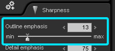 Use it to fix the overall level of the sharpness.
(2) Detail emphasis
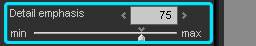 Use it to fix the emphasis level of fine edge (detail).
When increasing this parameter, you can improve resolution of the detail without emphasizing outline.
However, this function emphasizes noise at the same time, keep balance with noise level.
* Detail emphasis level changes according to both of (1) outline emphasis parameters and this parameter. When decreasing (1) outline emphasis, detail emphasis also becomes smaller at the same time. At first, make rough adjustments by (1) outline emphasis parameter and then, adjust with this parameter.
(3) False outline ctrl.
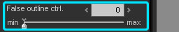 Use this to adjust the level to control false black or opposite coloring which appearing around the outline when the sharpness is increased.
However, when this parameter is increased, color separation doesn't work well (The color in the color boundary between different colors is lost and the area becomes white).
Keep this parameter and the color separation in balance.
(4) Type
4.7.3 Noise Reduction AdjustmentThe preset value provides you the parameters balanced well, but you can also set them manually to make more precise adjustments.
When switching to "Sharpness" sub-control, three sliders appear. The details are explained below.
Please refer to '10.1.8 Creating Extremely Clear Image' to make complete adjustment for sharpness setting.
(1) Outline emphasis
Use it to fix the overall level of the sharpness.Use it to fix the emphasis level of fine edge (detail).When increasing this parameter, you can improve resolution of the detail without emphasizing outline.
However, this function emphasizes noise at the same time, keep balance with noise level.
* Detail emphasis level changes according to both of (1) outline emphasis parameters and this parameter. When decreasing (1) outline emphasis, detail emphasis also becomes smaller at the same time. At first, make rough adjustments by (1) outline emphasis parameter and then, adjust with this parameter.
Use this to adjust the level to control false black or opposite coloring which appearing around the outline when the sharpness is increased.However, when this parameter is increased, color separation doesn't work well (The color in the color boundary between different colors is lost and the area becomes white).
Keep this parameter and the color separation in balance.
There are two type of sharpness algorism, "normal sharp" and "pure detail".
"Normal sharp" is ordinary algorism.
"Pure detail" is ISL original algorism for higher resolution looking. It gives you stronger effect than with "normal sharp".
"Normal sharp" is ordinary algorism.
"Pure detail" is ISL original algorism for higher resolution looking. It gives you stronger effect than with "normal sharp".
Noise means the rough texture that occurs in high sensitive photography. We call it high frequency noise in the software.At the high sensitive photography, red, green, or blue spots appear, too. We call them color noise in this software.
The function to remove such noise is the noise reduction.
In this software, the noise reduction function has independent parameter for each category.
The following sections are summaries of the function of noise reduction.
4.7.3.1 False Color Control
The false color control function changes the process level of false color reduction.The software enables to reduce both false colors occur in the fine structure area (high frequency area) and color noise.
When too much color noise at high sensitive photography or false colors in the fine structure area occur, increases the reduction level.
However, there are some demerits in this function.
As the reduction level becomes stronger, the color separation level goes down, which makes colors in the color boundary blur. Also, there is a problem of "color spill," which is the phenomenon that occurs when the vivid color leaks around the picture.
Therefore, too strong reduction level may decrease the picture quality.
Use the "Noise reduction" slider in the "Noise reduction" sub-control to reduce the high frequency noise. This function reduces the noise, with using RAW data.Also, you can remove noise that often occurs when the sharpness is increased. Use the "Noise level" and the "Noise cancel" in the "Noise reduction" sub-control.
Refer to '10.1.8 Creating Extremely Clear Image' for the operation.
Color noise is false color, which is generated by noise, and often appears at high sensitive photography. Use the false color control function to modify.
To reduce false colors around the outline, which appear at the time of adjusting sharpness (it is not the noise, though), use the "false outline ctrl."
4.7.3.3.1 Noise Level
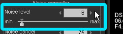 Fix the level of outline for outline emphasis with this parameter. The sharpness adjustment of this software only works toward the outlines above the setting of the noise level, and not effective for the outline or noise under that level.
Therefore, increasing this parameter may remove the noise, which is too noticeable.
However, as it becomes higher, the resolution especially in the detail becomes lower.
If you want to increase the resolution in the detail, set the lower noise level.
4.7.3.3.2 Noise Cancel
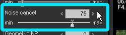 Specify the level to cancel the noise which is under the noise level set with the noise level function.
* If too much rough texture is seen in a photo, we recommend you to make the level higher to modify.
4.7.3.3.3 Geometric NR
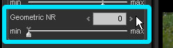
With some camera and under some condition, there is some geometric noise, which depends on the characteristics of the image sensor or image processing.
This function allows you to reduce such kind of geometric noise. Please check the effect with your camera.
When you use this function, please adjust the parameter value. Because too large value makes quality lower.
To reduce false colors around the outline, which appear at the time of adjusting sharpness (it is not the noise, though), use the "false outline ctrl."
4.7.3.3.1 Noise Level
Fix the level of outline for outline emphasis with this parameter. The sharpness adjustment of this software only works toward the outlines above the setting of the noise level, and not effective for the outline or noise under that level.Therefore, increasing this parameter may remove the noise, which is too noticeable.
However, as it becomes higher, the resolution especially in the detail becomes lower.
If you want to increase the resolution in the detail, set the lower noise level.
Specify the level to cancel the noise which is under the noise level set with the noise level function.* If too much rough texture is seen in a photo, we recommend you to make the level higher to modify.
With some camera and under some condition, there is some geometric noise, which depends on the characteristics of the image sensor or image processing.
This function allows you to reduce such kind of geometric noise. Please check the effect with your camera.
When you use this function, please adjust the parameter value. Because too large value makes quality lower.
4.8 Development
4.8.1 Demosaic Sharp Adjustment
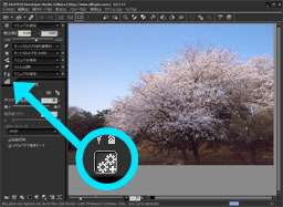 The "Demosaic sharp" in the "Development" sub-control fixes the development quality.
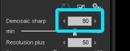 Normally, set this value around "80."
Set it lower for a picture with full of noise. Please refer to '10.1.4 Relation between Demosaic Sharp and Picture Quality' for more information.
You can change it temporary in order to speed up preview display. Please refer to '10.1.1 Speeding-up of Refreshing Preview' for your reference.
4.8.2 Resolution Plus
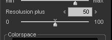
This function is only for RAF (RAW data) of FUJIFILM FinePix S3/S5 Pro with WIDE mode.
FinePix S3/S5 Pro has super CCD honeycomb SRII sensor, which has the structure of a low sensitive pixel (R pixel) between high sensitive pixels (S pixel).
SILKYPIX® can make full use of these information to increase the image resolution.
But it is very difficult to use the information of low sensitive pixel because it has only one 16th energy and high noise. Therefore it makes sometimes outline noise emphasized or jagged outline.
This function allows you to adjust the balance between the high resolution and noisy/jagged outline demerit.
If you set it 0, then SILKYPIX® does not use the information of low sensitive pixel for increasing resolution but for gradation always.
If you set it 100, SILKYPIX® makes full use of these information to increase the image resolution.
This parameter is influenced by "demosaic sharp" parameter. Please take the balance of these parameters.
4.8.3 Colorspace
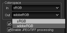
4.8.3.1 Input Colorspace
4.8.4 Auto Preview
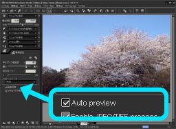
SILKYPIX® refreshes the preview image whenever the development parameter is modified as default setting.
This function allows you to keep quick response of GUI with low processing power PC by stopping auto preview refreshing.
Remove check for "Auto preview" on "Development" sub-control to disable "Auto preview" function.
Additionally there is a technique to make faster the preview refreshing. Please refer to '10.1.1 Speeding-up of Refreshing Preview'.
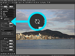 When you disable "Auto preview function, Click
  button on the toolbar or "Development" sub-control to refresh the preview manually.
4.8.5 JPEG/TIFF Processing Mode
You can switch enable/disable the function to process JPEG/TIFF image.
If you always take a photograph with RAW mode, you need not process JPEG/TIFF image usually. You can inhibit to process JPEG/TIFF image with this setting.
Additionally if you watch the development parameter recorded into JPEG/TIFF image which is developed by SILKYPIX®, please disable "JPEG/TIFF processing". Then you can watch the development parameter on each GUI of SILKYPIX®.
The "Demosaic sharp" in the "Development" sub-control fixes the development quality.Normally, set this value around "80."Set it lower for a picture with full of noise. Please refer to '10.1.4 Relation between Demosaic Sharp and Picture Quality' for more information.
You can change it temporary in order to speed up preview display. Please refer to '10.1.1 Speeding-up of Refreshing Preview' for your reference.
This function is only for RAF (RAW data) of FUJIFILM FinePix S3/S5 Pro with WIDE mode.
FinePix S3/S5 Pro has super CCD honeycomb SRII sensor, which has the structure of a low sensitive pixel (R pixel) between high sensitive pixels (S pixel).
SILKYPIX® can make full use of these information to increase the image resolution.
But it is very difficult to use the information of low sensitive pixel because it has only one 16th energy and high noise. Therefore it makes sometimes outline noise emphasized or jagged outline.
This function allows you to adjust the balance between the high resolution and noisy/jagged outline demerit.
If you set it 0, then SILKYPIX® does not use the information of low sensitive pixel for increasing resolution but for gradation always.
If you set it 100, SILKYPIX® makes full use of these information to increase the image resolution.
This parameter is influenced by "demosaic sharp" parameter. Please take the balance of these parameters.
4.8.3.1 Input Colorspace
You can specifically set the input colorspace for a JPEG/TIFF image by this control.
SILKYPIX automatically determines the input colorspace of a JPEG/TIFF image according to the standard of EXIF2.21.
When the JPEG/TIFF image does not include the colorspace information or when the colorspace is recorded by other way that is not based on the standard of EXIF2.21, SILKYPIX treats the image as sRGB colorspace.
When SILKYPIX cannot determine the correct colorspace, it may not be possible to do a right color reproduction. In this case, please set specifically the input colorspace by this control.
4.8.3.2 Output ColorspaceSILKYPIX automatically determines the input colorspace of a JPEG/TIFF image according to the standard of EXIF2.21.
When the JPEG/TIFF image does not include the colorspace information or when the colorspace is recorded by other way that is not based on the standard of EXIF2.21, SILKYPIX treats the image as sRGB colorspace.
When SILKYPIX cannot determine the correct colorspace, it may not be possible to do a right color reproduction. In this case, please set specifically the input colorspace by this control.
Select colorspace in "Colorspace" dropdown list in "Color" sub-control to decide the tone expression at development, working colorspace adjusted by the tone curve, and colorspace for image file created after development.
You can select "sRGB" or "Adobe RGB."
sRGB is the standard colorspace for Windows. Since Windows handles sRGB colorspace by default, use the software with the sRGB setting generally.
Adobe RGB is effective in processing the image, which was developed by this software, with a photo retouching software additionally, or in printing purpose.
It has wider color reproduction range than sRGB, but cannot be operated unless you have proper image processing environment to handle color profile (improper environment generates strange colors).
When reading files output by Adobe RGB with other software, set Adobe RGB colorspace for the profile setting (Operation varies depending on each software, so refer to the manual of the software you are using).
This software also enables to embed a color profile indicating the colorspace into an output file. A file with an embedded profile allows transferring the colorspace to the software supporting the color profile.
In addition, this software complies with Exif 2.21 Specification and outputs Exif information indicating Adobe RGB colorspace.
Please refer to '9.1 Setting for Developed Image' for embedding profile or Exif information output.
* When selecting Adobe RGB, preview is displayed based on Adobe RGB colorspace. Therefore, when the color management of monitor is not set, colors are displayed differently.
When selecting Adobe RGB, set the color management of monitor valid so that the correct colors are displayed. Please refer to '9.2.1 Color Management'.
SILKYPIX® refreshes the preview image whenever the development parameter is modified as default setting.
This function allows you to keep quick response of GUI with low processing power PC by stopping auto preview refreshing.
Remove check for "Auto preview" on "Development" sub-control to disable "Auto preview" function.
Additionally there is a technique to make faster the preview refreshing. Please refer to '10.1.1 Speeding-up of Refreshing Preview'.
When you disable "Auto preview function, Click button on the toolbar or "Development" sub-control to refresh the preview manually.You can switch enable/disable the function to process JPEG/TIFF image.
If you always take a photograph with RAW mode, you need not process JPEG/TIFF image usually. You can inhibit to process JPEG/TIFF image with this setting.
Additionally if you watch the development parameter recorded into JPEG/TIFF image which is developed by SILKYPIX®, please disable "JPEG/TIFF processing". Then you can watch the development parameter on each GUI of SILKYPIX®.
4.9 Highlight Controller
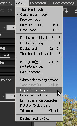 Highlight controller function controls color creation in highlight area.
The menu command [View(V)]-[Highlight controller] displays the "Highlight controller" sub-control.
This function controls a color clip in the highlight area, where one of color components (R, G, or B) is saturated. There are several types of controls. The "Chroma/Luminance" and the "Saturation/Hue" controls impact on the area where at least one of color components is saturated. The "Restoration" control restores the lightness of the area that was saturated wrongly at photographing with under exposure bias adjustment.
4.9.1 Emphasis on Chroma/Luminance
Chroma/Luminance controls the priority of chroma or luminance to create colors in the highlight area.
The following pictures were developed based on the RAW data with highlight area (flowers). They were developed with chroma, luminance, or intermediate between Saturation/Tone.
"Chroma" emphasizes the colors of the flowers, and "Luminance" controls the highlight area effectively to express the glare of the reflected light.
Here is another sample.
"Highlight controller" works effectively with the lighter area such as the sunset scene.
The following pictures, which are sunset scenes, were developed with each priority, chroma, luminance, and intermediate between them.
4.9.2 Emphasis on Saturation/HueThe following pictures were developed based on the RAW data with highlight area (flowers). They were developed with chroma, luminance, or intermediate between Saturation/Tone.
"Chroma" emphasizes the colors of the flowers, and "Luminance" controls the highlight area effectively to express the glare of the reflected light.
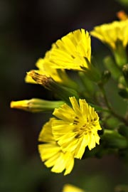 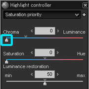 Chroma (value: 0) | 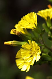 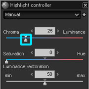 Intermediate (value: 25) | 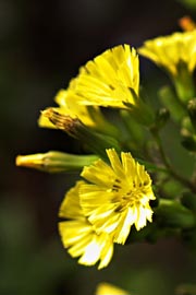 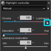 Luminance (value: 100) |
Here is another sample.
"Highlight controller" works effectively with the lighter area such as the sunset scene.
The following pictures, which are sunset scenes, were developed with each priority, chroma, luminance, and intermediate between them.
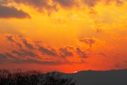 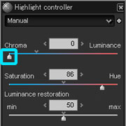 Chroma (value: 0) | 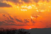 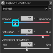 Intermediate (value: 25) | 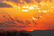 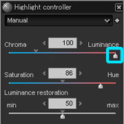 Luminance (value: 100) |
After giving priority to chroma with the "Chroma/Luminance" slider, you can also control the priority of saturation or hue to finish development process.
As shown below, since R value (red) of the orange flower in orange was saturated, the hue of the highlight area became yellowish.
In such case, emphasize the hue with the "Saturation/Hue" slider to prevent reverse of the hue.
This process is also effective for the highlight area of skin, which has become yellow.
In some cases, it is more helpful to give priority to saturation.
In the following picture (a bee and a flower), you can see the color of pink and yellow are nicely reproduced by putting priority on saturation.
4.9.3 Luminance RestorationAs shown below, since R value (red) of the orange flower in orange was saturated, the hue of the highlight area became yellowish.
In such case, emphasize the hue with the "Saturation/Hue" slider to prevent reverse of the hue.
This process is also effective for the highlight area of skin, which has become yellow.
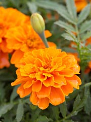 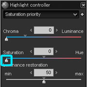 Saturation (value: 0) |  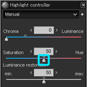 Intermediate (value: 50) | 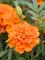 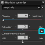 Hue (value: 100) |
In some cases, it is more helpful to give priority to saturation.
In the following picture (a bee and a flower), you can see the color of pink and yellow are nicely reproduced by putting priority on saturation.
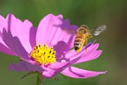 Saturation (value:0) | 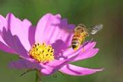 Intermediate (value: 50) | 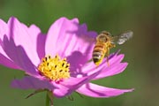 Hue (value: 100) |
This function restores original colors, which were lost by over-exposure photography.
In RAW data, the color information may be recorded correctly even though it is lost on the photo.
In such case, make the exposure bias under at the development and you can restore the tones recorded in RAW data.
However, the area where the sensor is saturated cannot be restored with this way. Restoration enables to restore the lost lightness information based on information provided with a sensor with lower sensitivity.
The left is a picture of RAW data, which was taken with exposure set to the trees and ground and developed without exposure bias. The center picture was developed with -2EV exposure bias. The tones of the sky and clouds were restored and you can check lens flare. The right picture was restored by restoration.
As you see, the sky and clouds become clearer with this operation.
In addition, the following example is created with the image combine of the upper left picture and the sky and clouds in the right picture.
This shows the best result with the restored sky and clouds, and appropriate exposure on the trees and ground. This sample takes full advantage of development based on RAW data.
When you create two types of developed pictures with different exposure bias and restoration parameters, and combine them with a photo-retouching software, you can operate such wide dynamic range and create a nice photo. This is the excellent advantage of RAW data.
4.9.4 Dynamic RangeIn RAW data, the color information may be recorded correctly even though it is lost on the photo.
In such case, make the exposure bias under at the development and you can restore the tones recorded in RAW data.
However, the area where the sensor is saturated cannot be restored with this way. Restoration enables to restore the lost lightness information based on information provided with a sensor with lower sensitivity.
The left is a picture of RAW data, which was taken with exposure set to the trees and ground and developed without exposure bias. The center picture was developed with -2EV exposure bias. The tones of the sky and clouds were restored and you can check lens flare. The right picture was restored by restoration.
As you see, the sky and clouds become clearer with this operation.
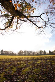 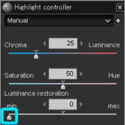 Restoration(value: 0), No Exposure Bias | 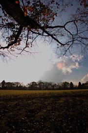 Restoration(value: 0), Exposure Bias(-2.0) | 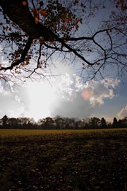 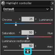 Restoration(value: 128), Exposure Bias(-2.0) |
In addition, the following example is created with the image combine of the upper left picture and the sky and clouds in the right picture.
This shows the best result with the restored sky and clouds, and appropriate exposure on the trees and ground. This sample takes full advantage of development based on RAW data.
When you create two types of developed pictures with different exposure bias and restoration parameters, and combine them with a photo-retouching software, you can operate such wide dynamic range and create a nice photo. This is the excellent advantage of RAW data.
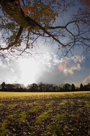 Composite Picture |
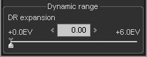
This function allows you to compress the highlight gradation.
If you set it larger value, you can make smooth gradation of highlight area or make detail expression of highlight area.
Please remember that you cannot use this function for overexposure scenes.
If you would like to make full use of this function, please take a photograph with a little underexposure and use "Exposure bias" function of SILKYPIX®.
This technique provides you enough information of highlight gradation, and you can freely adjust highlight gradation with this function.
If you use FinePix S3/S5 Pro with WIDE mode, you need not take a photograph with underexposure because it records about +2EV enough highlight information.
4.10 Fine Color Controller
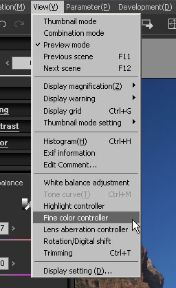 Fine color controller is a powerful tone adjustment function enabling to handle colors freely.
The menu command [View(V)]-[Fine color controller] displays the "Fine color controller" sub-control.
Move 8 points displayed on the control to handle colors.
The control displays all colors of all hue. Colors far from the center of the circle have high saturation.
This is a cross-sectional diagram uniform colorspace, where the colors are allocated as equal as possible to match human sense.
 Fine Color Control |
In this control, there are 8 operation points inside. Move these points to adjust colors.
You can drag the operation point near the target color with mouse to change saturation or hue. The sliders are also available for changing hue, saturation and lightness.
As you move the operation point to outside of the color circle, the saturation level becomes higher, and as you move the point inside, the level becomes lower.
You can change the hue by moving the point on the circumference of the color circle.
The selected point can be adjusted precisely with the slider above. You can change not only the hue and saturation, but also lightness with the slider.
[Mouse wheel operation]
You can operate the "saturation" slider with the mouse wheel on color circle GUI.
[SHIFT] key + mouse wheel is for the "hue" slider and [CTRL] key + mouse wheel is for the "lightness" slider.
(Please refer to [Adjusting with the sliders])
You can change colors you want with this function. There is no special theory.[SHIFT] key + mouse wheel is for the "hue" slider and [CTRL] key + mouse wheel is for the "lightness" slider.
(Please refer to [Adjusting with the sliders])
Use this control repeatedly to master the operation.
We recommend you to set the white balance, exposure and color mode before using this control.
When you changed the white balance to make the skin pinkish, and that operation caused the sky becoming purplish, you can change the hue of the purplish point to make the sky blue.
Also, you can change the color of the skin and sky with the moderate white balance first. Next, adjust the orange point to change the skin color to the level you want, and then change the color of the sky.
You may want to change colors uniquely on purpose, like making a red tulip a pink one, or changing purple to blue purple. Enjoy color variation and make your inspired vision a reality.
When you feel confused with such variety of options, select the color mode to create colors closer to your favorite ones first, and make fine adjustments.
The important feature of this function is modification of over-exposure in the high saturation area.
Especially when you try high saturation photo with the memory color or film tone V, the over-exposure occurs in the high saturation area.
In this case, decrease the level of saturation or lightness of the color to reduce this phenomenon. Please refer to '10.1.5 Modification of Overexposure' for more details.
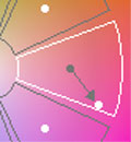 |
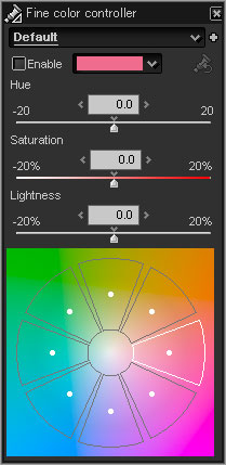 [Adjusting with the sliders]
| Hue | : | Set the angle in anticlockwise rotation from the reference point. |
| Saturation | : | Set the ratio assuming that the distance from the center of the color circle to the reference point is 100%. When setting -20%, the operation point moves to the inside by 20%, and the saturation level is decreased. When setting 20%, the point moves to the outside by 20% and the saturation level is increased. |
| Lightness | : | Set the ratio assuming that the lightness of the reference point is 100%. When setting -20%, the lightness level is decreased, and setting 20%, it is increased. |
| Initialize button | : | Return all points to the initial state. |
| Enable checkbox | : | Enable the fine color control. |
* This parameter category has Enable/Disable setting. Please refer to '4.14.1 Enable/Disable for Parameter' section.
[Example]
If you would like to adjust specific hue;
(1) Display "Fine color controller" sub-control with menu command [View(V)]-[Fine color controller].
(2) Move operation point on the each 8 colors section, you can adjust the specific hue of the target scene.
• Move operation point outer from the center of color circle, "saturation" is higher.
• Move operation point inner to the center of color circle, "saturation" is lower.
• Move operation point along the edge of color circle, "hue" is changed.
You can also adjust with 3 sliders control.• Move operation point inner to the center of color circle, "saturation" is lower.
• Move operation point along the edge of color circle, "hue" is changed.
With slider controls, you can adjust "lightness" additionally.
* When you move mouse pointer on the target color of preview image, the pointer is displayed on the color circle of this control.
It shows you which hue you should adjust.
Please adjust this parameter after adjusting "white balance", "exposure bias", and "color mode".
4.11 Lens Aberration Controller
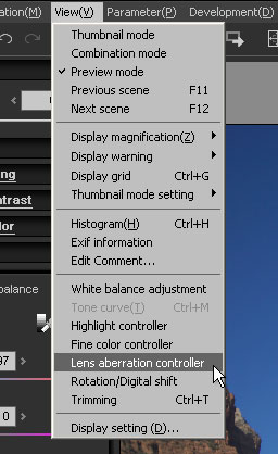 Lens aberration correction is a function to correct lens aberration at development in order to create high quality image.
The menu command [View(V)]-[Lens aberration controller] displays the "lens aberration controller" sub-control. The sub-control can be displayed also with the lens aberration controller button
 under the left.
Photo lenses have aberration. Today, the resolution of digital camera is improved, therefore, lens aberration may have a damaging effect on the picture quality. There are various kinds of lens aberration such as spherical aberration, coma aberration, astigmatism, curved field, distortion aberration, axial chromatic aberration, chromatic aberration of magnification, and shading reduction that is a decrease of light volume occurring in the periphery. To adjust these aberration three corrections are available:
shading, distortion, and chromatic aberration.
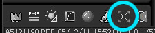
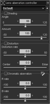
4.11.1 Shading (Peripheral Brightness Reduction) Correction
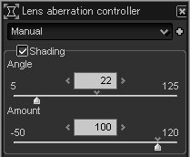 Shading correction is a function to correct light falloff at edges, which is a characteristic of a lens, making an area around the object darker. Use two parameters to correct shading.
 4.11.1.1 Angle of View
Input the diagonal angle of view of the lens at photographing.
On a lens, light volume is decreasing toward the periphery area. The angle of view is larger in a wide-angle lens and smaller in a telescopic lens. Based on conversion to 35mm film format (full size digital single-lens reflex camera), the angle of view of a 50mm standard lens is approximately 46 degrees, that of a 135mm telescopic lens is approximately 18 degrees, and that of a 35mm wide-angle lens is approximately 63 degrees. When you input the angle of view,shading correction of a lens is performed through the calculation of logical lens shading.
However, it does not always match to the actual shading at photographing (Please refer to '4.11.1.3 Detail of Shading Reduction'), please move the slider and find the best point using the value mentioned above.
4.11.1.2 Correction Ratio for Amount of LightOn a lens, light volume is decreasing toward the periphery area. The angle of view is larger in a wide-angle lens and smaller in a telescopic lens. Based on conversion to 35mm film format (full size digital single-lens reflex camera), the angle of view of a 50mm standard lens is approximately 46 degrees, that of a 135mm telescopic lens is approximately 18 degrees, and that of a 35mm wide-angle lens is approximately 63 degrees. When you input the angle of view,shading correction of a lens is performed through the calculation of logical lens shading.
However, it does not always match to the actual shading at photographing (Please refer to '4.11.1.3 Detail of Shading Reduction'), please move the slider and find the best point using the value mentioned above.
Input the ratio that you apply for the correction.
When you set the amount 0%, no correction is performed, and the amount 100%, the logical value calculated based on the angle is used. You can set the parameter up to 120%.
You can use this function to adjust the level of correction for the following cases. The case you want to remain the shading effect without complete correction since the shading is one of the tastes that are unique to a lens. Or a case that a bright object is on the periphery of a photo and when you make corrections it becomes too bright and lost.
You can also increase the shading level by setting minus value. Use the value to emphasize the center area on purpose by darkening the periphery, or to make the background quiet.
4.11.1.3 Detail of Shading ReductionWhen you set the amount 0%, no correction is performed, and the amount 100%, the logical value calculated based on the angle is used. You can set the parameter up to 120%.
You can use this function to adjust the level of correction for the following cases. The case you want to remain the shading effect without complete correction since the shading is one of the tastes that are unique to a lens. Or a case that a bright object is on the periphery of a photo and when you make corrections it becomes too bright and lost.
You can also increase the shading level by setting minus value. Use the value to emphasize the center area on purpose by darkening the periphery, or to make the background quiet.
 |
Although image formation is distorted in a wide angle lens, the lens periphery tends to be lighter as the object is much distorted.
For example, fish-eye lens prevents the shading effect by distorting the object in the lens periphery.
Also, in a certain type of lens, a lens aperture seen from an oblique direction becomes smaller (vignetting), and such lens causes larger shading effect in the periphery area than the logical features.
An aperture value also impacts on the shading level. When it is the minimum value, large shading is caused, and when it is a larger value, shading becomes smaller. Moreover, with a digital camera, oblique incidence to the image sensor causes shading.
Therefore, handle the angle of view only for your reference. Find the best-balanced point by yourself. It is helpful to understand that correction amount becomes smaller and correction between the center and periphery becomes linear when making the angle parameter smaller, and correction amount becomes larger especially in the periphery when making the angle parameter bigger.
When you find that most area is corrected well except the periphery area, make the parameter bigger to increase the light level in the periphery. When the relation between the most area and the periphery is contrary, make the parameter smaller.
Distortion correction is a function to correct distortion aberration, making the straight line distorted. Before using this function, check the "Distortion" checkbox.
4.11.2.1 Distortion Rate
4.11.3 Transverse Chromatic Aberration Correction4.11.2.1 Distortion Rate
See the right picture. When the image is distorted like a barrel, move the slider to the left to set minus value. Adjust the parameter with the slider to the point that the distorted line becomes straight. If the image is distorted like a pincushion, shown in the left picture, move the slider to the right to find the best point. If the slider stays at the center 0, no correction is performed. After the correction, you can compare the original image with the corrected image by checking and non-checking the "Distortion" checkbox.
4.11.2.2 Center/Edge Control Pincushion Shape |  After Correction |  Barrel Shape |
Determine which one should take priority, the center or edge to make distortion adjustment.
If the image around the center is distorted greatly even though the straight line at the corner is corrected well, move the slider to select the center priority. If the distorted level around the center is too weak, move the slider to an opposite side. The left picture shows the pillar was distorted because of lens distortion aberration. The right picture was created by correcting the left picture to make the pillar straight.
Repeat adjustments of this parameter and distortion rate in turn to correct most of distortion of photo lenses, which can be corrected almost completely. If you use this parameter properly, it is possible to correct or modify a lens having complicated distortion aberration.
Distortion adjustment trims side drops of a picture automatically and enlarges it to make its size same as the original one. When using "Expansion" of the trimming function, you can extract all pixels including side drop pixels generated by the distortion adjustment and pixels recorded in RAW data which is normally cut out. Please refer to '4.13 Trimming'.
Although the distortion adjustment function was originally created for correcting lens distortion aberration, you can utilize it variously. For example, you can modify a phenomenon that objects are printed in all directions in the periphery of wide-angle lens by emphasizing perspective or increasing distortion level. The process in this function is not a simple distortion correction often used in a photo retouching software. This is a special process simulating a real lens aberration based on the actual design of a photo lens.
The right picture below was created with the stronger distortion level than usual. In the left picture (the original), the bubble and faces are distorted because of distortion aberration. The distortion level in the right picture was so strong that the shapes of the objects were distorted, that has given them more natural looking.
You now have got the effect of the lens, which can change its distortion level freely. Enjoy various combinations of parameters, and find a new expression.
If the image around the center is distorted greatly even though the straight line at the corner is corrected well, move the slider to select the center priority. If the distorted level around the center is too weak, move the slider to an opposite side. The left picture shows the pillar was distorted because of lens distortion aberration. The right picture was created by correcting the left picture to make the pillar straight.
  Original |   After Correction (Amount: -15 Center/Edge: -27) |
Repeat adjustments of this parameter and distortion rate in turn to correct most of distortion of photo lenses, which can be corrected almost completely. If you use this parameter properly, it is possible to correct or modify a lens having complicated distortion aberration.
Distortion adjustment trims side drops of a picture automatically and enlarges it to make its size same as the original one. When using "Expansion" of the trimming function, you can extract all pixels including side drop pixels generated by the distortion adjustment and pixels recorded in RAW data which is normally cut out. Please refer to '4.13 Trimming'.
Although the distortion adjustment function was originally created for correcting lens distortion aberration, you can utilize it variously. For example, you can modify a phenomenon that objects are printed in all directions in the periphery of wide-angle lens by emphasizing perspective or increasing distortion level. The process in this function is not a simple distortion correction often used in a photo retouching software. This is a special process simulating a real lens aberration based on the actual design of a photo lens.
The right picture below was created with the stronger distortion level than usual. In the left picture (the original), the bubble and faces are distorted because of distortion aberration. The distortion level in the right picture was so strong that the shapes of the objects were distorted, that has given them more natural looking.
  Original |   After Correction (Amount: 50 Center/Edge: -50) |
You now have got the effect of the lens, which can change its distortion level freely. Enjoy various combinations of parameters, and find a new expression.
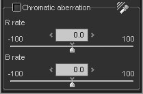 Transverse chromatic aberration correction is a function to correct false coloring on the edge around objects in an image. The transverse chromatic aberration is a disadvantage specific to an optical lens.
The transverse chromatic aberration is caused by the difference in lens magnification rates for each colored light (red light, green light, and blue light) incoming to a lens.
The transverse chromatic aberration correction is performed by changing R and B magnification slightly. First, enlarge the area, where the edge of an object in the image periphery is colored, to more than 400%, and display it (Please refer to '[Reason to enlarge more than 400% and selecting edge for proper correction]'). Then, decrease the false color control in the "Noise reduction" sub-control (for example, 0 - 80). After that, check the "Chromatic aberration" checkbox to adjust the R rate and the B rate.
When you correct a picture, enlarge the periphery area as shown below to check the correction result and change parameters.
4.11.3.1 R Rate
This adjusts the lens magnification for red light. If the edge is colored by red or cyan (complimentary color of red), change this parameter first.
4.11.3.2 B RateThis adjusts the lens magnification for blue light. If the edge is colored by blue or yellow (complimentary color of blue), change this parameter first.
When these two parameters are appropriate, coloring is decreased most.
First, look the edge condition and change the R rate so that "red <--> cyan" in the both sides of edge is decreased. Then change the B rate to adjust "blue <--> yellow" coloring. Repeat the R rate and B rate adjustments to find the best point.
Do not try to decrease coloring, but try to distribute the edge coloring uniformly. After that, when increasing the "False color ctrl" slider in the "Noise reduction" sub-control, the remaining colors are disappeared. Increase the parameter until you are satisfied, and finish adjustments.
At this time, if colors still remain even after the false color control is maximized, there is a possibility that transverse chromatic aberration is so big that it excesses the correctable range or that coloring occurs because of aberration other than transverse chromatic aberration. For example, too light background shows a possibility of coma aberration.
At the present time, aberration you can correct is only transverse chromatic aberration. Please refer to ' [Reason to enlarge more than 400% and selecting edge for proper correction]' for your reference.
4.11.3.3 Transverse Chromatic Aberration ToolWhen these two parameters are appropriate, coloring is decreased most.
First, look the edge condition and change the R rate so that "red <--> cyan" in the both sides of edge is decreased. Then change the B rate to adjust "blue <--> yellow" coloring. Repeat the R rate and B rate adjustments to find the best point.
Do not try to decrease coloring, but try to distribute the edge coloring uniformly. After that, when increasing the "False color ctrl" slider in the "Noise reduction" sub-control, the remaining colors are disappeared. Increase the parameter until you are satisfied, and finish adjustments.
At this time, if colors still remain even after the false color control is maximized, there is a possibility that transverse chromatic aberration is so big that it excesses the correctable range or that coloring occurs because of aberration other than transverse chromatic aberration. For example, too light background shows a possibility of coma aberration.
At the present time, aberration you can correct is only transverse chromatic aberration. Please refer to ' [Reason to enlarge more than 400% and selecting edge for proper correction]' for your reference.
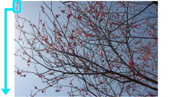 The Original Picture |
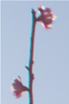 Before Correction | 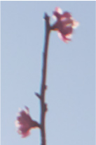 After Correction |
This tool allows you to adjust "R rate" and "B rate" by one action.
Click button to switch operation mode to "Transverse chromatic aberration tool", and drag the target rectangle area on the preview image.
Then "chromatic aberration" parameter is automatically calculated.
Please retry a few times with another position until you get the good result.
* Please refer to [Reason to enlarge more than 400% and selecting edge for proper correction].
[Reason to enlarge more than 400% and selecting edge for proper correction]Click
button to switch operation mode to "Transverse chromatic aberration tool", and drag the target rectangle area on the preview image.Then "chromatic aberration" parameter is automatically calculated.
Please retry a few times with another position until you get the good result.
* Please refer to [Reason to enlarge more than 400% and selecting edge for proper correction].
Enlarging preview with more than 400% stops simplified development and glare at the time of updating preview, so you can view images more easily. In transverse chromatic aberration correction process, it is recommended to set the preview ratio with more than 400% in order to check changes in the image and to adjust parameters. If updating preview according to parameter changes is too slow to handle, increase the preview ratio more, or make the window for displaying updated preview smaller.
It is preferable to select the edge you want to change when enlarging a display for adjustments. Please pay attention to the following points.
1. Do not select edges in too light (white) background.
It is preferable to select the edge you want to change when enlarging a display for adjustments. Please pay attention to the following points.
1. Do not select edges in too light (white) background.
The background of the sample is not lost, though, the tone of this picture is light and aberration appears in the twig against the background of the light sky. You should not select the point in such background for aberration correction. The white background is too shiny, and coloring is generated by not only transverse chromatic aberration but also by other aberration such as coma aberration or astigmatism that make difficult to adjust parameters.
2. Select an edge perpendicular to a radial line through the screen center as possible.Transverse chromatic aberration appears because of difference between the magnification for each color. Therefore, it hardly appears on the radial line through the screen center and often appears on the edge perpendicular to a radial line through the screen center. Selecting the edge perpendicular to the radial line makes parameter adjustments easier.
3. Select an edge in the periphery of the the target image as possible.Transverse chromatic aberration impacts most on the periphery of the screen. Coloring is becoming stronger in the area far from the center of the image. Check the edge in the image periphery to make adjustments.
4.12 Rotation/Digital Shift
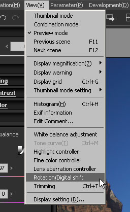 The menu command [View(V)]-[Rotation/Digital shift] displays the "Rotation/Digital shift" sub-control. The sub-control can be displayed also with the Rotation/Digital Shift button
  under the left.
* When you are changing "rotation/digital shift" parameter, grid is displayed automatically as default setting. (Please refer to '9.2.4 Grid Setting')
4.12.1 Rotation
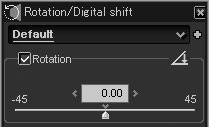 Rotation is a function to rotate an image.
With rotation function, a rectangle image with a certain aspect ratio is rotated and automatically trimmed to restore the original shape at the original aspect ratio. This process maintains the original number of pixels and prevents from resolution reduction after the rotation.
Therefore, you can use the rotation function at ease. This function works well on a slightly slant picture.
This software allows -45degree to +45degree rotation.
Then, by using the "expansion" in the trimming functions, the image is enlarged and trimmed so as to maintain the same pixels as the original image. Please refer to '4.13.5 Expansion of Trimming'.
4.12.1.1 Rotation Tool
"Rotation tool" can correct a slant horizontal/vertical line to a right attitude.
You can use this tool on "preview mode" or "combination mode". You can use the "rotation tool" by clicking menu command [Operation(M)]-[Rotation tool] or \imgv./img/ico_rot02.jpg button on the "Rotation/Digital shift" sub-control.}
Then the mouse cursor shows you "rotation tool" mode. In this mode, please trace the horizontal line or vertical line by mouse dragging.
Then the rotation angle is set automatically so as to correct the horizontal line or vertical line horizontally or vertically respectively.
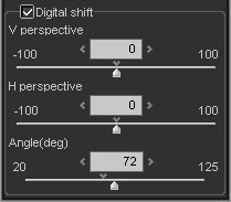 Digital shift has advantages such as shift lenses have.
With this function, you can make perspective control, or correct a distorted building to a straight one.
The "V perspective" slider can change the magnifications for the upper area and lower area of the image. When moving it to the left (smaller value), the magnifications for the upper area becomes larger, and to the right (large value), the magnifications for the lower area becomes larger. The "H perspective" slider can change magnifications for the left area and the right area of the image. When moving it to the left, the magnification for left area becomes and to the right, the magnification for the right area becomes larger.
The modified image shape becomes a trapezoid or distorted rectangle, however, it is automatically trimmed and modified to restore the original shape at the original aspect ratio. Therefore, the number of pixels maintain the original numbers, avoiding resolution reduction due to deformation.
In this case, the "expansion" of the trimming function is used. Please refer to '4.13.5 Expansion of Trimming.'
Digital shift works not only on a picture of buildings, but also on various kinds of photo. As you see in the picture below, you can make a person's face smaller and legs longer. In this picture, +6 (down: fall) is set for digital shift to correct the original, and you see that the legs become longer in the corrected picture.
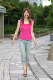 The Original | 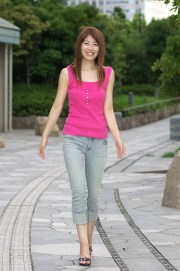 After Correction (V perspective: +6) |
The deformation of this process is not a simple conversion from a rectangle to a trapezoid, but the projection conversion from three-dimensional space to two-dimensional space. This is the same type of conversion when taking a picture of real three-dimensional objects with a camera. Then you can get the same effect of using a shift lens.
You have now got the lens which can shift freely. Try various combinations of parameters to find a new expression.
[Angle]
You will need information on angle of view of a lens in order to get the right effect of digital shift.
The default angle-of-view parameter is set almost properly based on the EXIF information on input file.
However, when you don't attach a manufacturer-made lens or attach an old lens, the angle of view may not be set properly.
If you find that the image is distorted vertically or horizontally after the digital shift process, adjust the "angle" parameter.
Frequent use of the "angle" parameter gives an impression as if the aspect ratio with digital shift changes.
Use that effect as one of unique expressions.
4.13 Trimming
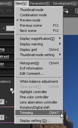 The menu command [View(V)]-[Trimming] displays the "Setting for trimming" dialog.
You can also operate this function by pressing [Ctrl]+T keys or the setting for trimming area button
 in the tool bar.
You can select any area in the image when doing development.
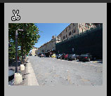 When setting trimming area, the trimming mark appears in the thumbnail at the thumbnail mode.
4.13.1 How to Set Trimming Area
(1) Select an aspect ratio of an image from the following options.
4.13.2 How to Operate Handle in Trimming AreaFree: The aspect ratio is not fixed. You can select any trimming area.
Fixed: Default fixed aspect ratio is used.
Specified: You can specify any aspect ratio.
Preset: You can select a preset to specify the size.
* For the default fixed aspect ratio, you can choose the horizontal format or the portrait format.
* When selecting "Fixed", the aspect ratio becomes fixed even if both of the trimmed image and non-trimmed image exist together (when the photos were taken with the same camera having the same settings).
* The aspect ratio set by this function is also used for trimming other images.
(2) Set the trimming size for the image. There are two ways to specify size.Fixed: Default fixed aspect ratio is used.
Specified: You can specify any aspect ratio.
Preset: You can select a preset to specify the size.
* For the default fixed aspect ratio, you can choose the horizontal format or the portrait format.
* When selecting "Fixed", the aspect ratio becomes fixed even if both of the trimmed image and non-trimmed image exist together (when the photos were taken with the same camera having the same settings).
* The aspect ratio set by this function is also used for trimming other images.
Input a value in Edit box in the upper area of the dialog directly.
Drag a handle of the trimming area displayed on the preview screen to change the size.
Drag a handle of the trimming area displayed on the preview screen to change the size.
(1) Set the area with each handle at every corner and every side.
(2) Move the area with the center handle.
(3) When clicking the round handle at the right of the center, the trimming area rotates by 90 degrees.
* In the mode except "Free", the trimming size is automatically adjusted so that the aspect ratio maintains the same value.
4.13.3 How to Operate "Setting for trimming" Dialog(2) Move the area with the center handle.
(3) When clicking the round handle at the right of the center, the trimming area rotates by 90 degrees.
* In the mode except "Free", the trimming size is automatically adjusted so that the aspect ratio maintains the same value.
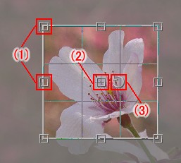 Trimming Area Handle |
(1) "Trimming area": The following values are displayed.
(2) Specifying a method: Select from the four potions: "Free", "Fixed", "Specified", and "Preset." | (A) Upper left coordinates (x,y) (B) Size (width x height) (C) One coordinates (x,y) for the area (D) The other coordinates (x,y) for the area |  Trimming area |
(3) Applying
 : Apply specified aspect ratio.
 (4) Initializing
 : Initialize it to default.
(5) Trimming tool
 : Switch to the trimming tool mode.
 (6) Expansion: All areas recorded in RAW are expanded so that they are used as the target area (Expansion area means the whole area used for image information stored as RAW data, and normally part of it is used as an effective area. In some models, black area and invalid image area are included).
 Setting for Trimming Area Dialog |
4.13.4 Trimming Tool
Click button to switch operation mode to "trimming tool" mode.
"Trimming tool" allows the mouse drag operation to specify the whole trimming area according to the "Specifying method".
If you select "Free" as "Specifying method", mouse dragging from the start point to end point creates a trimming rectangle.
If you select a method other than "Free", the aspect ratio of trimming area is fixed. Then the rectangle with the fixed aspect ratio is displayed by dragging the mouse from a starting point to an ending point. Thus you can adjust the trimming rectangle.
4.13.5 Expansion of Trimming button to switch operation mode to "trimming tool" mode."Trimming tool" allows the mouse drag operation to specify the whole trimming area according to the "Specifying method".
If you select "Free" as "Specifying method", mouse dragging from the start point to end point creates a trimming rectangle.
If you select a method other than "Free", the aspect ratio of trimming area is fixed. Then the rectangle with the fixed aspect ratio is displayed by dragging the mouse from a starting point to an ending point. Thus you can adjust the trimming rectangle.
The "Exp" button enables to handle all pixels including invalid pixels, which are cut out normally, and pixels cut out with distortion correction, rotation, and digital shift. When pressing this button, all these pixels are displayed, and you can select the trimming area.
Invalid pixels in RAW files are also displayed. Some pixels in a noise or black area may be displayed according to the type of a camera.
Invalid pixels in RAW files are also displayed. Some pixels in a noise or black area may be displayed according to the type of a camera.
4.14 Others
4.14.1 Enable/Disable for Parameter
Some kinds of development parameters have Enable/Disable setting for the parameter unit. "Fine color controller", "Lens aberration controller", and "Rotation/Digital shift" sub-controls have such setting.
"Fine color controller" has one "Enable/Disable" setting for the whole parameters, and "Lens aberration controller" has 3 settings for each separated parameter unit.
If this setting is "Disable", each parameter value within the unit is ignored.
[When the development parameter is copied]
4.14.2 Keyboard and Mouse Operation for Macintosh"Fine color controller" has one "Enable/Disable" setting for the whole parameters, and "Lens aberration controller" has 3 settings for each separated parameter unit.
If this setting is "Disable", each parameter value within the unit is ignored.
[When the development parameter is copied]
Please note the following behavior when copy operation is performed; This is copy operation from "Source" to "Destination".
If the "Source" setting is "Enable", "Destination" setting is set to "Enable" and each parameter value of the "Destination" is set to the same value as "Source".
If the "Source" setting is "Disable", "Destination" setting is set to "Disable" and each parameter value of the "Destination" is not changed.
This manual is described on the assumption that the mouse has 2 or more buttons and keyboard operation is for Windows PC.
Therefore if you use Macintosh PC, please pay attention for the following;
Right click
Therefore if you use Macintosh PC, please pay attention for the following;
Right click
[Control] key + mouse click is the same as "Right click" of the mouse.
[CTRL] key + Left click[Command] key + mouse click is the same as "[CTRL] key + Left click" of the mouse.
[ALT] key[Option] key is the same as [ALT] key.