4. How to Adjust Development Parameter
Adjustments to development parameters is performed through Parameters Controls and the GUI at the top of sub-controls.
We recommend that you adjust development parameters on SILKYPIX in the following order: Exposure bias, White balance, Tone, Color, Sharpening, and Noise reduction.
In order to make adjustments using this order easier, the GUI for each adjustment item is located in order from the top.
It is recommended that you make adjustments using the recommended flow by utilizing the parameters controls.
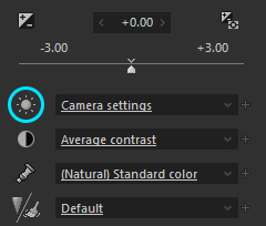
4.1. “Parameters Controls” and “Sub-control”
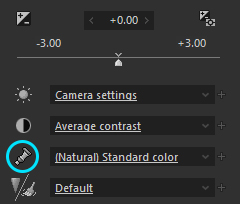
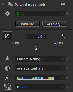 The GUI for setting each parameter is located in the Main Controls part at the top of Parameters Controls.
GUIs in the Main Controls are placed in the following order from the upside.
The GUI for setting each parameter is located in the Main Controls part at the top of Parameters Controls.
GUIs in the Main Controls are placed in the following order from the upside.
- Tastes/Parameters
- (Dropdown list + Select button + Parameter adjustment button)
- (Dropdown list + Select button + Parameter adjustment button)
- Exposure / Luminance
- (Slider control + Select button + “Automatic exposure bias” button)
- (Slider control + Select button + “Automatic exposure bias” button)
- White balance
- (Dropdown list + Select button)
- (Dropdown list + Select button)
- Tone
- (Dropdown list + Select button)
- (Dropdown list + Select button)
- Color
- (Dropdown list + Select button)
- (Dropdown list + Select button)
- Sharpening/Noise reduction
- (Dropdown list + Select button)
- (Dropdown list + Select button)
On the bottom area of the “Parameters controls”, sub-control icons to switch sub-controls for adjustment of the development parameter are located.
The dropdown list is the GUI for selecting a taste (=preset value) that is prepared in advance by ISL (Ichikawa Soft Laboratory) or a user.
The “taste” is a value consisting of development parameters. For more details about the “taste”, please refer to ‘4.1.1 Taste’.
When you select a taste from the dropdown list, the related sub-controls automatically appear on the “Tab page”. However, according to customer’s preference, the sub-controls can be located on the “Control box” or a floating window.
4.1.1. Taste
Taste is a preset value , like a collection of development parameters.
You can easily define a “taste” value for frequently-used development parameters.
Utilize maker tastes
Model development parameters are recorded in advance in SILKYPIX as maker tastes.
You can use these to easily make adjustments to development parameters.
Open the dropdown list and select a “Taste” to apply.
By doing so, the development parameter registered in tastes will be reflected.
There are both “Overall tastes” to replace all development parameters and “Partial tastes” for a set of part of the development parameters found in tastes.
Applying “Partial tastes” is an action equivalent to “Partial paste of development parameters.”Register development parameters often used as user tastes
Register development parameters which are used often can be saved as user tastes, making them easier to recall.
There are two ways to register to tastes, “All category tastes” for all development parameters, and other tastes registered as category units in development parameters.
Please refer to “4.1.1.3. Add taste” concerning how to register.
4.1.1.1. All category tastes
 The dropdown list of “All category tastes” located to the side of the
  icon at the very top of the main control section in parameters controls will be explained here.
Tastes that can be selected here are all category tastes intended as “All categories” of development parameters.
There are two kinds of tastes, “Overall tastes” and “Partial tastes” in “All category tastes.”
[Explanation of Display]
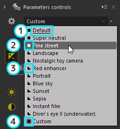
“Underlined displays” means default “taste”. When default values are defined as tastes, if the name of the concerned taste is different from the default value of any other registered taste, the name of the “Default” will be displayed as follows.
When a selected taste is displayed with green underlined font, it means that there are no development parameters file.
Please refer to “10.4.3.1. Development Parameter File and Collateral Information File” for detail of development parameters file. indicates that this taste is in “Overall tastes.”
If “Overall tastes” is selected, all categories of development parameters will be replaced. indicates that this taste is in “Partial tastes.”
If “Partial tastes” is selected, only a part of the categories of development parameters will be replaced.The
 mark indicates that this taste is currently selected.
If “Overall tastes,” one will be marked, and if “Partial tastes,” all that conform will be marked.
[Taste list for selection]
When you open the dropdown list, you can see and select the tastes on the list.
There are two kinds of tastes, one is “maker taste” prepared by us and the other is “user taste” defined by you. In addition, you can find the following items on the drop down list:Default
If you select it, the development parameters are reset to default parameter. However, if the default parameter is changed from “Default”, and the selected default parameter is the overall taste, the name of the registered overall taste will be displayed as the default value.Custom
Custom is displayed when the current taste does not match other existing tastes or the default parameter. Even if you select this taste, the development parameters will not be changed.Custom (Taste applied)
This shows the condition corresponding to one of the registered partial tastes, such as when a partial taste is applied.
Therefore, it will be displayed when the default parameter is changed from the “Default”, and the selected default parameter is a partial taste.
This item refers to the development parameter for the current setting, so the development parameter will not be changed even if selected.Default value (User settings)
This will be displayed if the default parameter is changed from the “Default” and the selected default parameter is a partial taste.
However, if this item is selected, it will be deemed to correspond to the registered partial taste, and the display for the taste will be “Custom (Taste applied)”.
[Display of the selected taste]
When the dropdown list is closed, the name of the current taste is displayed.
When one of registered tastes is selected, the name of the selected taste is displayed. The name of a partial taste is not displayed. Instead, one of the following is displayed: “Default”, “Custom”, “Custom (Taste applied)”.Default
This is displayed only when the development parameter matches with the “Default” of the default parameter.
If the default parameter is changed from the “Default”, and the selected default parameter is the overall taste, the name of the registered overall taste will be displayed as the default value.Custom
This indicates that neither results of adjusted development parameters nor registered tastes are in agreement.Custom (Taste applied)
This shows the condition corresponding to any of the registered partial tastes, such as when partial tastes are applied.
Therefore, it is displayed when the default parameter is changed from the “Default” and the selected default parameter is a partial taste
Please refer to “9.5. Default parameters settings” concerning default parameter.
* Partial taste is not displayed because the development parameters of the current taste can match those of two or more partial tastes at the same time. The mark of the “Partial taste” is displayed only when the dropdown list is opened.
4.1.1.2. Other tastes
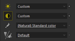 The following will explain dropdown lists of tastes other than “All category tastes”.
Dropdown lists for these tastes are located in the main control and at the top of each sub-control.
Dropdown lists, except for “All category tastes” located in the main control section, are, in order from the top:
- [White Balance Taste]
- [Tone Taste]
- [Color Taste]
- [Sharpening/Noise Reduction Taste]
When the sub-controls “White balance”, “Tone”, “Color”, “Sharpening” and “Noise reduction” are displayed as floating windows, these dropdown lists will have the following in common with dropdown lists located at the top of each sub-control.
[Target parameter category]
These dropdown lists are used to select partial tastes for only one parameter category.
If a taste other than “All category taste” located in the main control section is selected from a dropdown list, only development parameters that can be adjusted by the sub-control displayed on the tab page will be influenced.
If a taste is selected from these dropdown lists located at the top of the sub-control, only the development parameter that can be adjusted by the same sub-control (*1) will be influenced.*1 “Sharpening” and “Noise reduction” sub-controls are an exception. Its sub-controls are divided to two parts despite one parameter category.
Taste list for selection
When you open the dropdown list, you can see and select the tastes on the list.
There are two kinds of tastes, one is “maker taste” prepared by us and the other is “user taste” defined by you. In addition, you can find the following items on the drop down list:Default
If you select it, the development parameters are reset to default. However, this default value refers to the “Default” of the default parameter.Default value (User settings)
This is displayed if the default parameter is set to something other than the “Default” and the currently set development parameter is equivalent to the default parameter.
Please select this to return the development parameter to the selected default parameter.Custom
Custom is displayed when the current taste does not match other existing tastes or the default taste. Even if you select this taste, the development parameters will not be changed.
Display of the selected taste
When dropdown list is closed, the name of the current taste is displayed.
When one of registered tastes is selected, the name of the selected taste is displayed. But the name of a partial taste is not displayed.
Otherwise, the following items are sometimes displayed.Default
This is the display when the development parameter matches the “Default” of the default parameter.Default value (User settings)
This is displayed when the default parameter is set to something other than the “Default” and the currently set development parameter is equivalent to the default parameter.Custom
This indicates the status that the results of adjusted development parameters are not in agreement with any of the registered tastes.
4.1.1.3. Add taste
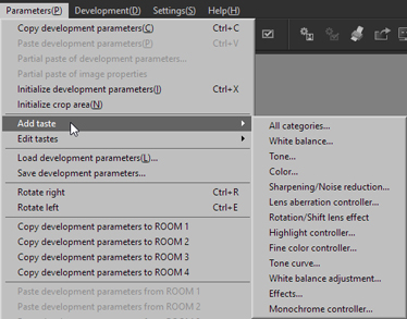 You can add / register a development parameter applied to a currently selected image as a taste.
There are two ways to add / register a taste.
Select [Taste category] from [Parameters (P)]-[Add taste] on the menu, or click on the  icon located on the right side of the dropdown list.
The “Add parameters taste” dialog will be displayed.
The “Add parameters taste” dialog format is the same as the “Edit parameters tastes” dialog.
Please see the next section, “4.1.1.4. Edit tastes” concerning operation methods for this dialog.
“Tastes” added through the “Add parameters taste” dialog will be displayed in dialogs as selected, so set an appropriate name for the taste and click on the [OK] button to confirm.
Items set in the “Add parameters taste” dialog
Taste name
By default, names are set sequentially, such as “User taste 1.”
Change to an appropriate name to make it easy to distinguish from other tastes.Applicable development parameter category
If “Taste category” is added as a taste other than “All categories,” it is not necessary to edit because “Applicable development parameter category” is fixed to one category.
If the “Taste category” is “All categories,” you can enable any category in “Applicable development parameter category.”
Enabled categories are set as taste masks.
4.1.1.4. Edit tastes
You can edit registered tastes.
You can customize by changing taste names and the order they are displayed to make it easier to select tastes.
You can also save / restore tastes and move then to other PCs through export and import functions
“Add parameters taste” is performed from [Parameters (P)]-[Edit tastes]-[Parameters tastes] on the menu.
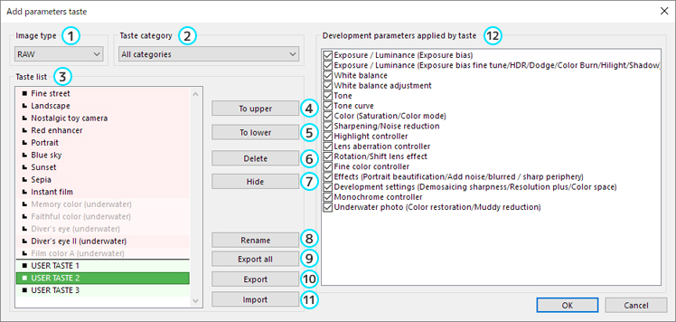
Subject data
A taste is defined for a “RAW” or a “JPEG/TIFF”. You can select either of the two types.Taste category
A taste is defined for each parameter category.List of tastes
There is a list of tastes with a mark.- A mark at the left of a taste title:
The taste represents all development parameters if you select taste category “All parameters”.
The taste only part of the parameters if you select taste category “All parameters”.
There are two kinds of tastes, maker tastes created in advance by our company, and user tastes that you create. - Maker taste
These are displayed with a red background.
They cannot be deleted, exported or moved. - User taste
These are displayed with a green background.
- A mark at the left of a taste title:
Upward button
The upward button moves a selected taste upward.Downward button
The downward button moves a selected taste downward.Delete button
The Delete button deletes selected tastes.
Maker tastes cannot be deleted.Hide / Show button
Selected data is hidden.
Maker data cannot be deleted, but they will not be displayed on the list of tastes with this setting.Rename
Change the name of selected tastes.Export all button
All user tastes that have “Image type” and “Taste category” in common are recorded and saved in a file.
All tastes displayed with a green background are “Taste list”.Export button
The export button exports a single selected taste.Import button
The import button imports a saved taste.Development parameters applied by taste
When you select the “All parameters” in the list of the taste category, you can apply any of the parameter categories to a taste. For example, you can apply “tone” and “tone curve” to a taste.
When you add a new taste, the “Edit parameters tastes” dialog is also displayed and you can customize a name of a new taste and other settings as well as the taste customizing.
4.1.2. Tastes/Parameters
 You can perform taste registration and editing, save development parameters, read, initialize and temporarily register in the “Tastes/Parameters” sub-control.
4.1.2.1. Storerooms
The “Storerooms” is a function that temporarily records development parameters.
There are four rooms (ROOM 1-4) in which you can record development parameters. There is also a special room named “Latest”.
You can record optional development parameters in the first four rooms.
Development parameters for the currently selected image are recorded in a room by clicking the o button on the left side.
When development parameters are recorded in a room, the time they were recorded is displayed.
Rooms with recorded development parameters are turned into buttons, and when you click this button, the development parameters recorded in the room are pasted onto the currently selected image.
In this way, you can copy development parameters from other images and past development parameters from the same image.
Rooms with recorded development parameters that match the development parameters of the currently selected image are displayed in bold.
The  icon on the right side is a button for entering “Continuous paste tool”.
“Continuous paste tool” is a mode for pasting development parameters recorded in a room to multiple images. Click on a scene in the thumbnail display to paste development parameters.
In order to leave this tool, click on the icon again.
The special room, “Latest”, located at the bottom always stores the latest edited development parameters.
Use this when you want to paste the latest results from adjusted development parameters to other images.
There are several convenient ways to use the “Storerooms”.
Please see “6.5. How to Use Storerooms” for details.
4.1.2.2. Hot folder 
“Hot folder” is a function for monitoring a selected folder and automatically adding images to thumbnails if an image for processing is added.
This function can be used only when a single folder is selected.
By clicking on a button reading “No data” within the border of the “Hot folder”, the development parameter of the selected image will be registered and a check will appear in the check box next to “Enable”.
While “Enable” is checked, images to which registered development parameters are applied are automatically added.
The check next to “Enable” is automatically removed when the selected folder is changed.
4.1.2.3. Display the default parameters
Make settings for the “Display the image with default parameters while holding down” button.
Please refer to “3.2.3. Displays of images with default parameters by mouse operations” for information about this function.
4.1.3. Parameter adjustment buttons
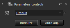 “Initialize” and “Auto adjustment” buttons are located under “All category tastes”.
4.1.3.1. Initialize
Reset the development parameters of selected images to default.
If default parameters are set, the default parameters will be applied.
Please refer to “7.4. Initialize Development Parameters” for details.
4.1.3.2. Auto adjustment
The “Auto adjustment” button adjusts to the optimal exposure, white balance, and level correction for SILKYPIX all at once.
Clicking the “Auto adjustment” button will perform the following adjustments in order for the selected images.
For auto white balance, “Auto (Natural)” will be set.
Automatic level correction will be performed on the “RGB” channel.
Further adjustments can also be made to parameters after performing auto adjustment.
Please use this function according to each situation.
4.1.4. Control box
 Multiple sub-controls can be located in a control box.
Sub-controls for parameter categories in the main control are located at the top of the control box as tab pages.
A control box is added is “Arrange control box” is selected from the menu on the title bar through sub-controls in floating windows.
When an added sub-control is selected from an icon or menu under Parameters controls, the control box is scrolled and the selected sub-control is displayed.
4.2. Sub-control
Sub-control is prepared for each parameter category. The types can be classified by function (A - F) and by default location (1 - 4).
- [List of sub-controls]
| Type | Sub-controls |
|---|---|
| (E) - (1) | Tastes/Parameters |
| (A) - (1) | Exposure / Luminance |
| (A) - (1) | White balance |
| (B) - (2) | White balance adjustment |
| (A) - (1) | Tone |
| (B) - (2) | Tone curve |
| (A) - (1) | Color |
| (A) - (1) | Sharpening (*1) |
| (A) - (1) | Noise reduction (*1) |
| (A) - (2) | Development settings (*2) |
| (B) - (2) | Highlight controller |
| (B) - (2) | Fine color controller |
| (B) - (2) | Lens aberration controller |
| (B) - (2) | Rotation/Shift lens effect |
| (B) - (2) | Effects |
| (B) - (2) | Monochrome controller |
| (B) - (2) | Underwater photo controller |
| (C) - (2) | Crop tool |
| (C) - (2) | Spotting tools |
| (C) - (2) | Grid settings |
| (C) - (2) | Partial correction tool |
| (D) - (3) | Histogram |
| (D) - (4) | Image properties |
| (D) - (2) | Batch development status |
| (D) - (4) | Folder |
| (D) - (4) | Navigator |
| (E) - (2) | Editing history |
| (F) - (2) | Color management |
[Type of sub-controls]
(A) This sub-control is for adjusting basic category parameters found in development parameters.
The drop down list for tastes is located in the Main Controls, and if located in the Control Box, is also displayed within the Control Box.(B) This sub-control is for adjusting parameters belonging to parameter categories for minute adjustments found in development parameters.
(C) This sub-control runs and displays tool modes in the preview display.
It is displayed only when switching to the concerned tool mode.(D) This sub-control is for displaying information. It is not a control for operating parameters.
(E) This sub-control is for performing operation on tastes and development parameters.
(F) This sub-control is displayed in connection with the warning mode of the preview display.
It is displayed only when switched to the concerned warning mode.
*1 “Sharpening” and “Noise reduction” sub-controls are divided into two sub-controls, but they share a common parameter category.
Tastes are shared.*2 “Development settings” do not have tastes.
[Classifications of Sub-control Initial Locations]
(1) This sub-control is located on the Tab Page.
(2) This sub-control is displayed as a floating window.
(3) This sub-control is located on the right side of the main window.
(4) This sub-control is located on the left side of the main window.
4.3. Exposure / Luminance
Adjust the brightness of images.
In exposure correction, the brightness of an entire image will be adjusted.
If the entire image is too dark or too bright, it can be adjusted to the appropriate brightness.
In the Exposure / Luminance sub-control, the brightness of the bright areas and dark areas will be adjusted.
Objects with considerable differences in brightness can be adjusted to an appropriate balance, and dark areas that are hard to see can be made brighter so that they can be seen.
4.3.1. Exposure Bias
4.3.1.1. Exposure Bias
 You can determine exposure bias using a development gain when developing. This results in very similar exposure bias on a camera with processes equivalent to the push-process and pull-process on film.
You can perform adjustments by selecting an a value from the exposure bias slider.
You can determine exposure bias using a development gain when developing. This results in very similar exposure bias on a camera with processes equivalent to the push-process and pull-process on film.
You can perform adjustments by selecting an a value from the exposure bias slider.
You can take a photograph on the premise that you can adjust exposure bias at development process later. Please refer to ‘10.1.2. Utilizing Difference between Exposure Biases of Camera and SILKYPIX’ for more details.
4.3.1.2. Auto Exposure Bias
 Exposure bias can be performed automatically by clicking the Automatic exposure bias button.
The algorithm for automatic exposure bias in SILKYPIX detects an object and analyzes its colors in detail. While restricting brightness and washed-out colors, it performs strong that employs the best of our image processing technology in order to utilize the ability to reproduce colors on your monitor or printer.
This is a quick way to getting the perfect exposure for your images, even if you underexpose your pictures a little. Slight underexposure is typical for RAW photography, as it prevents the highlight areas from loosing structure. This feature helps reduce time when adjusting development parameters.
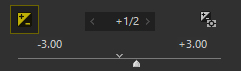
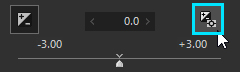
4.3.1.3. Fine-Tuning Exposure Bias
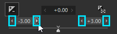 You can fine-tune your exposure with the spin-button that shows the highest and lowest values for exposure. This allows for more detailed adjustments to your exposure that cannot be done on the exposure bias slider.
We recommend that you make rough adjustments to exposure bias and then fine-tune it with the fine-tuning exposure bias.
4.3.1.4. Exposure bias tool
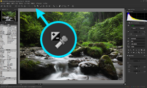 Exposure bias tool allows you to adjust the brightness of a specified point to a certain exposure level.
To adjust exposure level, you select “Exposure bias tool” from the menu [Tools (T)]-[Exposure bias tool], or click
Exposure bias tool allows you to adjust the brightness of a specified point to a certain exposure level.
To adjust exposure level, you select “Exposure bias tool” from the menu [Tools (T)]-[Exposure bias tool], or click  on the toolbar.
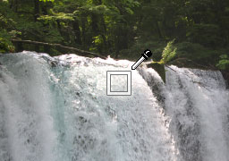 When you designate an area by either clicking or dragging on a preview image or thumbnail of a selected image, “Exposure bias tool” adjusts the brightness of the selected area to become the “luminance level”.
The “luminance level” is specified as the photosensitive level on the RAW data. You can change it in the “Function settings” dialog. Please refer to ‘9.3.1.2. Luminance level of exp. bias tool’ for more details.
When you designate an area by either clicking or dragging on a preview image or thumbnail of a selected image, “Exposure bias tool” adjusts the brightness of the selected area to become the “luminance level”.
The “luminance level” is specified as the photosensitive level on the RAW data. You can change it in the “Function settings” dialog. Please refer to ‘9.3.1.2. Luminance level of exp. bias tool’ for more details.
This function works effectively even when a specified point is not achromatic color. In that case, the largest value of R, G, or B is selected as a target value and the exposure is set to the “luminance level”.
For example, when you click the red area, this feature sets an “exposure bias” such that the R value becomes the “luminance level”.
* About eyedropper operation, please refer to ‘9.3.2. Operations’.
4.3.2. “Exposure / Luminance” sub-control
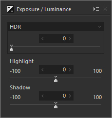 In the Exposure / Luminance sub-control, you can adjust dodge / color burn / HDR and highlight / shadow.
4.3.2.1. Dodge / Color Burn / HDR
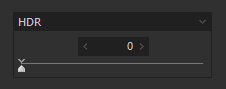 You can adjust Dodge / Color Burn and HDR.
Select the adjustment item from the drop down list and make adjustments to the appropriate amount with the slider.
Only the adjustment item selected from the drop down list will be applied. You cannot use multiple adjustment items at the same time.
4.3.2.1.1. Dodge / Color Burn
Dodge is a technique for reducing exposure to photographic paper and adjusting partial brightness by covering dark parts in a printing process for wet photographs.
On the other hand, color burn is a method of making parts brighter by increasing exposure to the photographic paper for bright parts under a process for color burning on silver halide photography.
If the subject shows large differences in brightness, performing exposure bias to correspond with the darker portions will make the brighter areas too bright.
In such a case, by using dodge / color burning techniques to adjust to an appropriate amount of exposure bias to each area of the image, you can finish your photographs with higher gradation.
The dodge / color burning adjustments included in this software analyzes images and automatically distinguish between parts that do not have enough exposure and those that do, and then performs an exposure bias on those parts with a precision close to that of the human eye.
It reduces the exposure in areas that are too bright and adds exposure to dark areas, by adjusting each area to achieve a balanced brightness.
It is effective on images of subjects that have a great differences in brightness that come from areas of overexposed and underexposed conditions, where the dynamic range can be reduced to make bright portions and dark portions easy to view lower overall contrast differential.
You can adjust the amount of dodge / color burn to suit, so try experimenting to see its effect.
In addition, you can select the following items as adjustments for dodge / color burn.
Color Burn
You can automatically search for bright parts such as overexposure, and restore the tone through desensitization.
In addition, this is applied only to bright areas and has no influence on the brightness of dark areas.Dodge
You can automatically search for dark areas and reproduce brightness through sensitization.
In addition, this is applied only to dark areas and has no influence on the brightness of bright areas.Dodge / Color Burn
This adjusts dodge and color burn at the same time.
* The “Dodge” adjustment item in SILKYPIX Developer Studio Pro 5 and earlier versions is handled as “Dodge / Color Burn” in SILKYPIX Developer Studio Pro9 / 9.
4.3.2.1.2. HDR
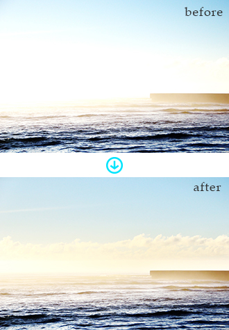
HDR is short for High Dynamic Range imaging. It is a technique for photographic imagery that comes close to human memory.
Photographs cannot simultaneously image bright parts and dark parts. If you adjust exposure to the bright parts, the darker parts will break down, and if you adjust exposure to the dark parts, the brighter parts will break down. However, the human eye continually processes the luminosity and recognizes it as an image. Therefore, even when, for example, you look at a scene with great differences in brightness, you recall the image without breaking down the whites or darks.
Put simply, HDR is a photographic technique for imaging in a much wider dynamic range compared to normal photographic techniques.
Many conventional HDR techniques use a method of combining multiple images of different exposure to create a single image. This software employs HDR imaging from the data of a single image by utilizing the wealth of information found in the image data to the maximum.
Please search for the most effective adjustments as you adjust HDR to perfection.
In addition, you can select the following items as HDR adjustments.
Color Burn HDR
You can automatically search for bright parts such as overexposure, and restore the tone through desensitization.
In addition, this is applied only to bright areas and has no influence on the brightness of dark areas.Dodge HDR
You can automatically search for dark areas and reproduce brightness through sensitization.
In addition, this is applied only to dark areas and has no influence on the brightness of bright areas.HDR
This adjusts bright areas and dark areas at the same time.

Reproduce brightness only on dark areas.
Reproduce darkness only on bright areas.
4.3.2.2. Highlight / Shadow
In Highlight / Shadow, the brightness of the bright and dark areas of an image is adjusted.
This software analyzes images and automatically identifies bright and dark areas.
Dark areas that are hard to see can be made brighter so that they can be seen, and discontinuity In the tone of clouds can be restored.
4.3.2.2.1. Highlight
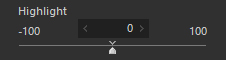 Adjust the brightness of the bright areas of images.
Adjustments can be made by selecting adjustment values using the Highlight slider.
4.3.2.2.2. Shadow
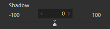 Adjust the brightness of the dark areas of images.
Adjustments can be made by selecting adjustment values using the Shadow slider.
4.4. White Balance
White balance is the function to adjust white color.
Human eyes adjust to ambient light color. We perceive the white color of an object as the same under sunlight, tungsten lamps, and fluorescent lamps. However, digital cameras, “white” under sunlight can be recorded as white, while white under tungsten lamps are recorded as a reddish white, similarly fluorescent lamps are recorded as greenish or bluish white. What provides compensation for these color shifts is “white balance”.
White balance adjustments vastly change colors in photos. A white object in the photo can be expressed most accurately and naturally with this function. In other words, the basic concept of white balance is the method of expressing white as white, irrelevant of color tint.
However, it is not always true for all types of scenes.
For example, if a white object in evening glow is expressed as a clean white, you will not be able to perceive this as sunset scene. If you want to produce a melancholy mood on your picture in a cloudy sky, it may be appropriate to add a blueish tint.
Although most cameras today can automatically adjust the white balance, it is not always accurate and even if it is correct, the result is not always what you intend. Therefore, it becomes necessary to adjust the white balance according to your artistic expression. However, it is very difficult to select and correct the white balance when taking a picture.
When taking a photograph in RAW, you do not have to consider a white balance setting since it is deemed a parameters only required in the process of developing RAW data into JPEG and TIFF images.
White balance settings in digital cameras are required for development processing in the camera and for converting to JPEG / TIFF images. It is not absolutely necessary to save them to RAW data.
The set white balance is reflected in preparing preview displays for displaying in thumbnail images and liquid crystal displays on the back of the camera. Therefore, it is desirable to set a value as appropriate as possible, but you can freely change the white balance while processing developments later.
If you take a picture with RAW data, you can change the white balance to what you want when you are developing the photo for a particular expression of a scene. One of the major advantages of using the RAW data is this function.
4.4.1. Adjusting White Balance with Taste
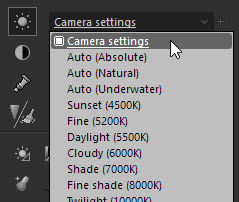 This is the way to make adjustment by selecting the white balance adjusted for each light source in advance. Select a taste that specifies a light source in the dropdown list of “white balance”.
You can also change settings in detail later, so it is convenient to select the light source first.
The preset items displayed in the dropdown list may be different for each type of camera.
There are “taste” that are prepared in the dropdown list of “white balance”, which specify each light source.
This is the way to make adjustment by selecting the white balance adjusted for each light source in advance. Select a taste that specifies a light source in the dropdown list of “white balance”.
You can also change settings in detail later, so it is convenient to select the light source first.
The preset items displayed in the dropdown list may be different for each type of camera.
There are “taste” that are prepared in the dropdown list of “white balance”, which specify each light source.
Auto (Absolute)
This automatically determines a suitable white balance. It automatically makes adjustments to cancel out color from the light source and color cast.Auto (Natural)
This automatically sets an appropriate white balance. It automatically adjusts in order to perceptually reproduce the atmosphere of the light source color. It is effective for retaining the color tone of the light source without completely correcting color cast from the light source color.Auto (Underwater)
This automatically sets an appropriate white balance. It automatically adjusts in order to remove blueness from the underwater photograph.Daylight
White balance suitable for shooting outdoors(Sunset)
White balance suitable for shooting in the direct sunlight of the evening glow(Fine)
White balance suitable for shooting in the direct sunlight of daytime in fine weather(Daylight)
White balance suitable for shooting in the direct sunlight in fine daytime (including obscured sky)(Cloud)
White balance suitable for shooting in scattered light from clouds in overcast day(Shade)
White balance suitable for shooting objects in the shade in fine daytime (including obscured sky)(Fine shade)
White balance suitable for shooting objects in the shade in clean and sunny daytime(Twilight)
White balance suitable for shooting in the direct sunlight of the twilight
Fluorescent
White balance suitable for shooting objects under fluorescent lightThree-band fluorescent
White balance suitable shooting objects under three-band fluorescent light widely used in homeTungsten
White balance suitable for shooting objects under incandescent lampFlash
White balance suitable for shooting objects in the photoflash
4.4.2. Auto White Balance
If “Auto (Absolute)” / “Auto (Natural)” is set in white balance, it will analyze the image and automatically adjust to a suitable white balance.
Don’t worry. You can use the “auto white balance” function, which expresses a light source color in white automatically.
The method and logic of “auto white balance” of SILKYPIX is fundamentally different from “auto white balance” in cameras. And it allows very accurate detection of the white balance of high color saturation or an object having no white area, which typical “auto white balance” function cannot handle well.
There is no correct white balance.
Only “you,” the one taking the picture, can make this determination based on what you want the photograph to express.
However, if many photographs are being developed, setting an appropriate white balance for each photograph would be a lot of work.
You can utilize Auto White Balance as a step for efficiently determining the white balance in many photographs.
Expressing white things in white is the basis of white balance.
Ultimately, when you adjust white balance for effective production, it would be best to start your work by first adjusting to an appropriate white balance so that white things are shown as white.
If you use Auto White Balance, most photographs will be automatically adjusted to an appropriate white balance, so if you are making adjustments to many photographs, first try using Auto White Balance to improve the efficiency of your work.
There are two types of auto white balance: “Auto (Absolute)” and “Auto (Natural)”.
“Auto (Absolute)” automatically makes adjustments in order to eliminate color casting from the light source color as much as possible.
“Auto (Natural)” automatically makes adjustments in order to perceptually reproduce the atmosphere of the light source color. It is effective for retaining the color tone of the light source without completely correcting color cast from the light source color.
4.4.3. Color Temperature and Color Deflection
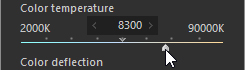
 This is the way to adjust the white balance by specifying the color temperature.
There is a “color temperature” adjustment slider on the “White balance” sub-control.
This is the way to adjust the white balance by specifying the color temperature.
There is a “color temperature” adjustment slider on the “White balance” sub-control.
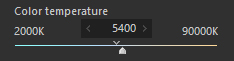 Move this slider to find the point where colors of the object are well balanced.
When the color of the object is reddish or yellowish, move the slider to decrease the color temperature.
When the color of the object is bluish, move the slider to increase the color temperature.
Move this slider to find the point where colors of the object are well balanced.
When the color of the object is reddish or yellowish, move the slider to decrease the color temperature.
When the color of the object is bluish, move the slider to increase the color temperature.
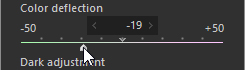
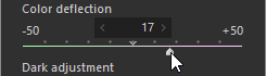
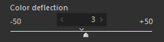 The “Color deflection” slider is used to remove color casts. Before using it, adjust the color temperature first.
When the color of the object appears greenish, move the slider to the + side.
When the color of the object appears magenta, move the slider to the - side.
The “Color deflection” slider is used to remove color casts. Before using it, adjust the color temperature first.
When the color of the object appears greenish, move the slider to the + side.
When the color of the object appears magenta, move the slider to the - side.
* Refer to ‘10.4.1. Color Temperature and Color Deflection’ for your information.
4.4.4. Gray balance tool
This is a tool for adjusting white balance, targeting the gray subjects that appear in the photograph.
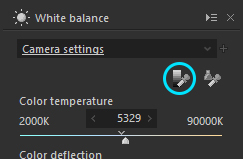 To adjust white balance in the “Gray balance tool” mode, you click “Gray balance tool” on the “White balance” sub-control, select “Gray balance tool” from the menu [Tools (T)]-[Gray balance tool], or click
  on the toolbar.
Then, click or drag the area that you want to change gray to specify the range. The white balance will be set to express that area in gray.
When there is a gray object in a photo, you can easily adjust the white balance with this function. Taking a photograph of a gray chart or white paper in advance may be very helpful.
* For eyedropper operation, refer to ‘9.3.2. Operations’.
4.4.5. Skin color tool
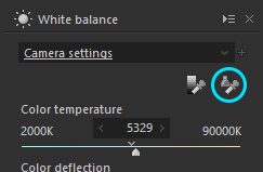 This is a tool for adjusting the skin of a person appearing in the photograph to an “expected pretty skin color”.
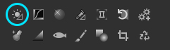
You can switch to “Skin color tool” with the  button on the “white balance” sub-control, or menu command [Tools (T)]-[Skin color tool].
In the “Skin color tool” mode, you can click or drag a rectangle area at the target skin on the preview, then the target area is automatically adjusted to beautiful skin color and also exposure bias is adjusted.
button on the “white balance” sub-control, or menu command [Tools (T)]-[Skin color tool].
In the “Skin color tool” mode, you can click or drag a rectangle area at the target skin on the preview, then the target area is automatically adjusted to beautiful skin color and also exposure bias is adjusted.
This tool is used at the same time as adjusting white balance and exposure bias.
 There are times when adjusting skin color does not change as expected with one operation.
If the result is too red, green, or blue, please click that area again. By a few repeatable operations, you can find out the suitable skin color.
Then you can additionally adjust “White balance adjustment”, “Exp. bias fine tune”, or “Tone” for fine-tuning.
If you use this tool on the woman’s face, please avoid the emphasized make-up area. Basic foundation area, especially dull color area is suitable for picking up,
* To adjust skin color continuously, you need to check “Enable Continuous Operation of Eyedropper Tool” on the “Function settings” dialog. Please refer to “9.3.2. Operations” for detail.
4.4.6. Gray balance tool for underwater photo
With the Gray balance tool for underwater photo, you can designate parts of the photo you want expressed in gray (neutral colors), which automatically adjusts the white balance so that those parts are expressed in gray, as well as calculating the color depth and underwater color deviation.
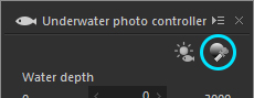 The White Balance Adjustment Mode is activated through the Underwater Gray Balance Tool by either selecting [Tools (T)] - [Gray balance tool for underwater photo] from the Menu, or by clicking on the
  button under Marine Controller.
Under this status, you can click on the portion of the preview image you wish to Gray, or you can designate the range by dragging. This will set the portions for white balance to be expressed in Gray.
This is an especially effective method when white objects (or objects with no color or of neutral color) are shown in the picture. Even if not completely white, you can drive this by using the color depth and underwater color deviation after using rough white balance by clicking on sandy areas or such.
* For eyedropper operation, refer to ‘9.3.2. Operations’.
4.4.7. Dark Adjustment
 While “color temperature” and “color deflection” change the white balance of the entire image, the “dark adjustment” amends color casts of the dark portion of the image.
Green or magenta color casts sometimes occurs in the dark portion although the white balance of the bright portion in a scene is well.
In this case, you can amend color casts with this function, and you can continuously remove color fluctuation from the dark portion to the bright portion.
While “color temperature” and “color deflection” change the white balance of the entire image, the “dark adjustment” amends color casts of the dark portion of the image.
Green or magenta color casts sometimes occurs in the dark portion although the white balance of the bright portion in a scene is well.
In this case, you can amend color casts with this function, and you can continuously remove color fluctuation from the dark portion to the bright portion.
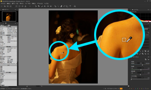
For example, the left picture is an illustration of strong magenta casts in the dark portion.
Looking at the enlarged portions, you can see that darker portions have magenta in them. You can alleviate this phenomenon through using white balance only in the darker areas by adjusting them. The picture on the right is a sample of a photograph with the magenta casting removed from the darker areas using the dark adjustment function.
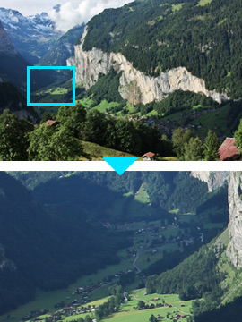
No corrections.
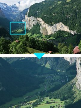
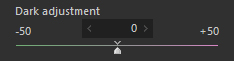
Dark Adjustment (Set value: -31)
Detail of color casts in the dark area
The main purpose of the function is to remove color casts in the dark area, however, with this function, you can also change the white balance of the dark area and bright area.
The left picture shows the photograph as shot.
The picture in the center shows when white balance is set to “Fine,” adjusting to meet the parts lit by sunlight in the back. However, the sunshine filtering through the foliage changes the color of the clothes greenish. If you use white balance on the color of the clothes, those colors will turn to magenta. In other words, you cannot achieve a balance between both the clothes and the sunlit portions using only white balance. Of course, since the sunlight is actually filtering through the foliage, the clothes look greenish and the center photograph reproduces the proper colors. However, as humans adapt colors, we feel the image is different from when the photograph was shot. In this type of case, you can adjust the white balance on the darker areas with dark adjustment. The photograph on the right is an example of removing the greens without changing by much the brighter areas lit by the sun with dark adjustment. This is quite close to the image at the time the photograph was shot.
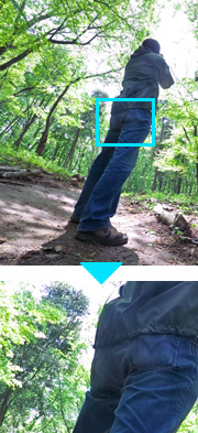
No Correction

White Balance (Fine:5200K)

White Balance (Fine), Dark Adjustment (+50)
Using with “color temperature” and “color deflection”
When adjusting the white balance, first determine the white balance of brighter parts with color temperature and color deflection. Next, perform dark adjustment if you want to remove color casting in darker areas.Detail of color casts in the dark area
Why do color casts occur in the dark portion?
This is caused by current leakage of an image sensor. Because of the leakage current, the intense black is not recorded as zero value in RAW data. SILKYPIX is subtracting such leakage current data from RAW data (optical black correction) to develop an image. However, a higher temperature increases leakage current of an image sensor, and vice versa. In most cases, a camera records black with constant level, regardless of the temperature, but some conditions or photographing environment may affect the level (optical black level). According to the color sensitivity of each image sensor, as the optical black level becomes larger, the color of the dark area becomes magentish, and as the level becomes smaller, the color becomes greenish. The “dark adjustment” function reduces coloring of the dark portion in those cases. It also corrects the white balance of the dark portion when a photograph is taken under severe conditions such as extremely low temperature, high-sensitive photography, and long exposure.
You can make corrections without affecting brighter areas (except when parameters are in compatible mode) because dark adjustment is reflected after exposure bias from SILKYPIX Developer Studio Pro 5.
4.4.8. Multi-light source compensation
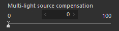 This function automatically distinguishes and adjusts white balance when there are two or more different light source colors within the same image.
Mixed light refers to pictures where there are two or more different light source colors within the same image. For example, you may have a flash photograph while outdoors in the sunlight, causing a mixture of sunlight and the flash, or you may be indoors with light coming from a window, causing a mixture of outdoor and indoor lighting.
“Multi-light source compensation” alleviates part of the light source colors that are unnatural by adjusting the color temperature and color deflection.
You can adjust bias as necessary.
4.4.9. White Balance Adjustment
 The menu command [View (V)]-[Sub-controls]-[White balance adjustment] displays the “White balance adjustment” sub-control.
Use this function when you want to adjust the white balance at the final stage of your workflow e.g. tinting
You can adjust white balance in detail with this sub-control, which has a “white balance target” graphic control, a “saturation” slider, and a “hue” slider.
The menu command [View (V)]-[Sub-controls]-[White balance adjustment] displays the “White balance adjustment” sub-control.
Use this function when you want to adjust the white balance at the final stage of your workflow e.g. tinting
You can adjust white balance in detail with this sub-control, which has a “white balance target” graphic control, a “saturation” slider, and a “hue” slider.
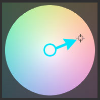
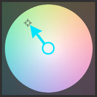
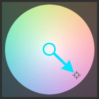
White balance target
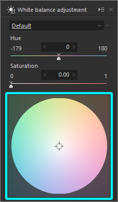 This graphic control is based on the accurate color space. You can set the white balance visually by clicking a mouse directly.
- [Mouse wheel operation]
You can change “saturation” parameter with the mouse wheel on the white balance target.
And with [Shift] key, you can change “hue” parameter.
- [Mouse wheel operation]
“Hue” slider
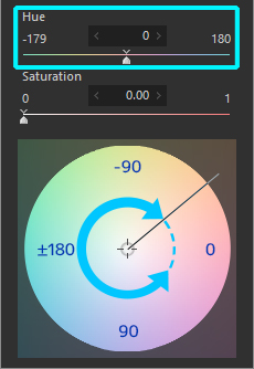 It shows the angle from the right hand side of the white balance target in clockwise. Move the slider to change the angle in detail.
You can specify the setting value indicates:
It shows the angle from the right hand side of the white balance target in clockwise. Move the slider to change the angle in detail.
You can specify the setting value indicates:- 0
right from the center - 90
downward from the center - 180
(-180)
left from the center - -90
upward from the center - +
lower half from the center - -
upper half from the center
- 0
“Saturation” slider
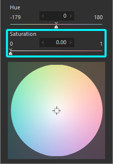 It shows the radius from the center of the white balance target. Move the slider to change the radius in detail. The range is 0.00 to 1.00 (0.00 is the center of the white balance target, 1.00 is the maximum radius).
4.4.10. Summary of Color and Adjustment
We will now introduce you some setting samples to show how to get the colors you want.
To remove reddish color (red casts)
- (a) Move the “Color temperature” slider to the smaller (lower) side.

- (b) With the white balance target in the “White balance adjustment” sub-control, move the cursor to the opposite (blue) direction.

- (a) Move the “Color temperature” slider to the smaller (lower) side.
To remove bluish color (blue casts)
- (a) Move the “Color temperature” slider to the larger (higher) side.
- (b) With the white balance target in the “White balance adjustment” sub-control, move the cursor to the opposite (red) direction.
- (a) Move the “Color temperature” slider to the larger (higher) side.
To remove purplish color (magenta casts)
- (a) Move the “Color deflection” slider to the - side.
- (b) With the white balance target in the “White balance adjustment” sub-control, move the cursor to the opposite (green) direction.
- (a) Move the “Color deflection” slider to the - side.
To remove greenish color
- (a) Move the “Color deflection” slider to the + side.
- (b) With the white balance target in the “White balance adjustment” sub-control, move the cursor to the opposite (purple) direction.
- (a) Move the “Color deflection” slider to the + side.
4.5. Tone
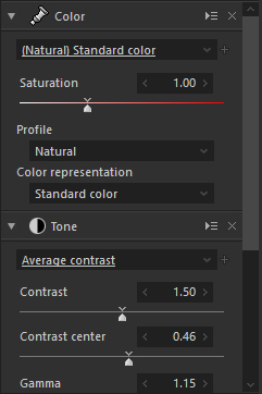
 Tone adjustment parameter adjusts the contrast, high or low.
Use the “Tone curve” for making minute adjustments after you finish adjusting other biases.
4.5.1. Adjusting Tone with Taste
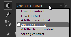 Select a taste from the dropdown list of “Tone”.
Tones in incremental steps from Low to Strongest are included as maker tastes.
“Average contrast” is the SILKYPIX default setting. “Average contrast” is a higher contrast than that obtained using sRGB and Adobe RGB standard tone curves, and is set to improve the overall appearance of an image.
Setting to “Standard” will give similar contrast levels to sRGB and Adobe RGB standard tone curves.
4.5.2. Fine-Tuning Tone
“Tone” adjustment can also be made to “Contrast”, “Contrast center”, “Gamma”, and “Black level”.
Clarity and Dehaze can also be adjusted.
Contrast
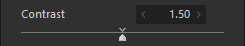 Contrast means the difference between bright area and dark area.
When increasing the contrast, the bright area becomes brighter and the dark area becomes darker, i.e. high contrast.
On the contrary, when decreasing the contrast, difference between the bright area and dark area becomes smaller, i.e. low contrast.
Contrast means the difference between bright area and dark area.
When increasing the contrast, the bright area becomes brighter and the dark area becomes darker, i.e. high contrast.
On the contrary, when decreasing the contrast, difference between the bright area and dark area becomes smaller, i.e. low contrast.Contrast center
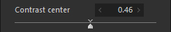 This is the reference to judge the brightness when adjusting the contrast. Upper levers from the contrast center are considered bright, and lower levels are considered dark. In other words, this reference decides the point where the brightness level is not changed when adjusting the contrast.
When setting the contrast center smaller, the tone of an image becomes lighter.
This is because the contrast is increased based on the dark area, and causes the dark area to become smaller and the bright area larger.
This is the reference to judge the brightness when adjusting the contrast. Upper levers from the contrast center are considered bright, and lower levels are considered dark. In other words, this reference decides the point where the brightness level is not changed when adjusting the contrast.
When setting the contrast center smaller, the tone of an image becomes lighter.
This is because the contrast is increased based on the dark area, and causes the dark area to become smaller and the bright area larger.
For example, by strengthening the contrast, “Bright areas” become brighter and “Dark areas” become darker, but “Mid contrast” is the midpoint between “Bright areas” and “Dark areas,” and there will be no influence on contrast.
When setting the contrast center larger, the tone of the image becomes darker.
While, setting the contrast center smaller, the tone of the image becomes brighter with the mid contrast level expanding.
Therefore, if a target object is dark, set the contrast center smaller, and if it is bright, set the contrast center larger to obtain an ideal tone.- [Utilizing Histogram]
Mid contrast is displayed with the mark at the bottom of the histogram.
The brightness of R, G, B where the mouse cursor is pointed to on the preview display is also displayed here.
When you use this function to adjust while looking at brightness distribution on parts you want to use contrast, you can find the optimal value relatively easily.
- [Utilizing Histogram]
Gamma
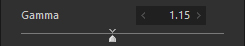 Gamma is a brightness adjustment. As the gamma increases, the overall brightness becomes higher, and vice versa.
You may think it is the same as exposure bias operation, however, they are not the same thing.
Gamma is a brightness adjustment. As the gamma increases, the overall brightness becomes higher, and vice versa.
You may think it is the same as exposure bias operation, however, they are not the same thing.
With the exposure bias, the brightness is adjusted without changing the ratio of bright range and dark range . However, with gamma, the ratio is changed.
When increasing the gamma value, the bright range is compressed, and the dark range is expanded.
When decreasing the gamma value, the dark range is compressed and the bright range is expanded.
Therefore, in this software, this operation is considered as a tone-change-operation and classified as ‘Tone Adjustment’ since it changes tone.Black level
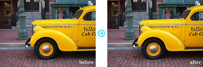
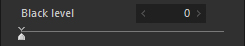 Black level controls create clarity of the dark areas.
You can specify the level of black with this function. When increasing this parameter, the color black becomes deeper black. This function works effectively when a picture is taken against the sun and the image becomes unimpressive, or when a landscape image becomes washed out, or when a landscape image becomes obscured or influenced by haze.Clarity
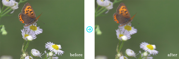
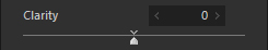 Clarity adjusts the fine texture of the subject.
If you increase clarity, you can refine the details of the subject more clearly, so if you want to revive the texture of a sleepy landscape photograph as a whole, this will have that effect.
In addition, if you lower clarity, you can finish with a soft focus and atmosphere such as with portraits of women and children or macro image.
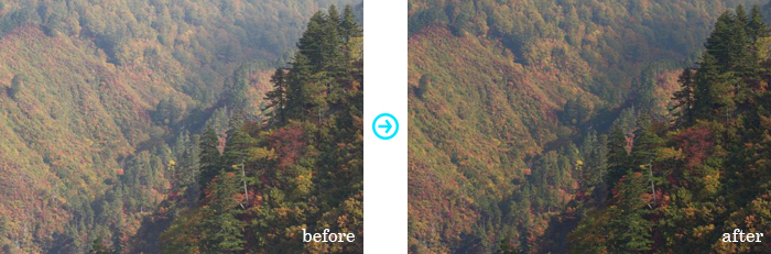
Dehaze
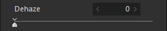 Dehaze restores and emphasizes the lost saturation in hazy areas due to dust.
Increasing the level of Dehaze will remove hazy areas and produce clear images.
Show tone on “Tone curve”
By placing a check next to ‘Show tone on “Tone curve”’, you can display the status of adjustments here in a graph in the “Tone curve” sub-control.
By adjusting the “Tone” parameter when displayed as a graph in the tone curve, you can visually confirm the parameter status in the graph.
Displaying the “Tone” graph can also be useful when making further minute adjustments on the “Tone curve”.
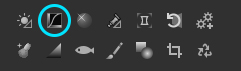
4.5.2.1. Black level tool
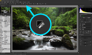 This tool designates and sets the black level on designated points or areas.
Enter “Black level tool” mode through either [Tools (T)] - [Black level tool] from the menu or with the  icon on the toolbar.
When you designate an area by either clicking or dragging on a preview image or thumbnail of a selected image, the black level will be adjusted on that area to the set brightness level.
The brightness level used here is the level of exposure in the RAW data. You can set the brightness level at “Function settings”. Please see “9.3.1.3. Luminance level of the black level tool” for details.
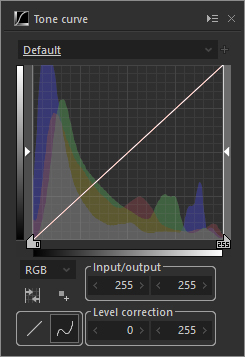
4.5.3. Tone Curve
 The “Tone curve” is a tool for making minute adjustments to tone expression after completing adjustments to other biases and for converting brightness for effect.
The menu command [View (V)]-[Sub-controls]-[Tone curve (T)] displays the “Tone curve” sub-control.
You can also display it using the sub-control icon “Tone curve” button.
Bias from the “Tone curve” is reflected after other bias processing is performed and converted to the color space on the output color space of development settings.
Therefore, for example, if you set monochrome to color, when you adjust R, G and B separately on the Tone curve, this will not be monochrome, or if you change the output color space in the development settings, you will have to make readjustments to match the color space. Keep this point in mind when you use this.
You can set the curve (= Tone curve) that converts brightness on this sub-control.
The horizontal axis means input (brightness of source picture) and the vertical axis means output (brightness results of a picture after adjustment). You can control lightness in a picture by operating this curve.
* By dragging window’s frame of the “Tone curve” sub-control, you can adjust a size of the dialog.
In addition, by dragging it while pressing the Shift key, you can adjust the size while fixing the aspect ratio of it.
4.5.3.1. Selecting a Taste
Several tastes that have good effects are included as Maker Tastes in tastes.
There are also special items such as “Initialize” and “Initialize all” within the tastes of the tone curve.
“Initialize” initializes only the tone curve of the selected channel (all RGB, R, G, B or L), while “Initialize all” initializes all five tone curves.
4.5.3.2. Editing Points
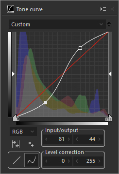 The curve is drawn as passing through a point, and you can operate the curve by moving the point.
Selected point information is displayed on the “Input / Output” control.
You can move the point by editing the value in this control or by dragging the point on the tone curve.
Adding Point
Click the mouse on a graph to place a point at the position.
You can also click to switch to a mode that will add a point to the tone curve and add a point from the preview display.
Selecting a point
Select a point for operations.
The selected point is displayed with .
.
You can switch selections by clicking the point with the mouse.Moving Point
You can move the composition point by either dragging the selected composition point on the graph or by changing the coordinate value of the composition point shown in the “Input/output” control.Deleting Point
Move and right-click the mouse on the target point to delete.
In addition, you can delete the current point by pressing the
4.5.3.3. Control explanation
Channel selection
Select a channel for processing.
The process is reflected in order of tone curve settings for each R, G, B, and L first and then tone curve setting for RGB.RGB
Set gradation process for all RGB values with the tone curve.R
Set gradation process for R value with the tone curve.G
Set gradation process for G value with the tone curve.B
Set gradation process for B value with the tone curve.L
Set gradation process for L (Luminance) value with the tone curve.
* When changing tones, colors are changed with brightness on tone curves combined with general RGB channels.
Because you can adjust only the tone of brightness with the L tone curve, color omissions and changes in chroma are decreased, even when using high key or high contrast, for example.Add point
Switch to a mode for adding a point to the tone curve.
The point clicked on the preview display adds a point to the tone curve.
By clicking the point while pressing the Ctrl key, you can add a point on all tone curves of RGB, R, G, B, and L.Linear
Create a tone curve at the interpolation of a straight line between points.Curve
Create a tone curve at the interpolation of a curved line between points.Input / output
Edit selected point coordinates.Level correction
Edit input range of level correction.Automatic level correction
This is a function that automatically adjusts level correction on the currently selected channel.
It recognizes the image’s histogram and adjusts the level correction so that shadows and highlights are to the set ratio.
Ratios of shadows and highlights can be set at “Function settings”.
Please see “9.3.1.7. Set automatic level correction” for details.* The “Add point” function works only when the tone curve is monotone increase or monotone decrease.
[How to use “Add point” function]
Click “Add point” button to add the target tone point on the tone curve.Select the target image on the preview window.
Display the “Tone curve” sub-control and click on the “Add point” button.
Switch to a mode to add a point on the tone curve.Click the target point on the preview image.
Then the target point is added on the tone curve.
Move the point and adjust the tone curve.
Moving the point edits the coordinate value by dragging the point on the tone curve or with the “Input / Output” control.Then the tone curve that you adjusted is applied to the target image.
4.6. Color Adjustment
 Color adjustment can be performed by selecting Color saturation adjustment, Color profile and Color representation.
4.6.1. Adjusting Saturation with Taste
 Select a taste from the dropdown list of “Color”.
4.6.2. Fine-Tuning Saturation
The taste includes a range of saturation that is considered to be appropriate to normal use. However, if you want more or less saturation, or adjust saturation more precisely, you can set it manually.
4.6.3. Color profile
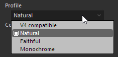 Color profile refers to the characteristics of Color representation. Select this from the “Profile” dropdown list in the “Color” sub-control.
Color profiles include “V4 compatible,” “Natural,” “Faithful,” “Monochrome,” “JPEG/TIFF,” “DNG,” “Photo style/Camera color” and “FILM SIMULATION.”
V4 compatible
“V4 compatible” is a profile that passes down color creation when there is parameter information in SILKYPIX Developer Studio Pro or SILKYPIX Developer Studio 4.0 or earlier. Please use if color tones were adjusted in previous versions.Natural
“Natural” is a profile that creates colors standard to SILKYPIX.Faithful
“Faithful” features color representation with plain harmonies. Even if you change the contrast with tones, color taste will be maintained. Therefore, you will be able to raise contract without over saturation and lower contrast without colors fading.Monochrome
“Monochrome” is used when making a monochrome photograph. You can choose from two different kinds of color representations under “Color representation”.JPEG/TIFF
“JPEG/TIFF” is a profile when image data is either JPEG or TIFF.DNG
“DNG” uses color profiles saved on DNG formatted images.
Please see “10.4.4. DNG (Digital Negative) format compatibility” concerning DNG formatted images.Photo style/Camera color
“Photo style/Camera color” is a profile to reproduce color creation by Panasonic digital cameras, and user can select this when you take RAW data by one of applicable cameras.
When you select “Photo style/Camera color,” “Color representation” will be changed to dedicated item “Photo style/Camera color.” You can select available photo style or “Camera color” which represents basic camera colors.
You can see digital cameras which are capable of “Photo style/Camera color” in “Supported cameras list.”* “Photo style” is one of functions by Panasonic digital camera.
FILM SIMULATION
“FILM SIMULATION” is a profile to reproduce color creation by FUJIFILM digital cameras, and user can select this when you take RAW data by one of applicable cameras.
When you select “FILM SIMULATION,” “Color representation” will be changed to dedicated item “FILM SIMULATION.” You can select available film simulation.
You can see digital cameras which are capable of “FILM SIMULATION” in “Supported cameras list.”* “FILM SIMULATION” is one of functions by FUJIFILM digital camera.
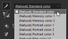
4.6.4. Color representation
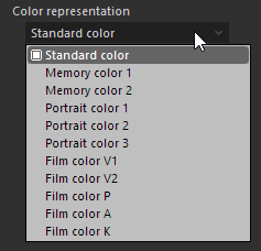 Color representation determine the direction of color reproduction. You can select it from the “Color representation” drop list in the “Color” sub-control. The following are categories of color representations: “Standard color,” “Memory color,” “Portrait color,” “Film color,” “Monochrome,” “Photo style/Camera color” and “FILM SIMULATION.”
4.6.4.1. Standard color
This is the standard color creation of SILKYPIX, which aims for true color reproduction. This mode provides reasonably natural colors for many scenes.
4.6.4.2. Memory color
True colors in photo are not always “beautiful colors.”
It is common knowledge that colors in our memory, or colors of an object that we perceive are different from actual colors. Although they differ in individuals, we can see a trend and directional characteristic.
We consider the picture “beautiful” when colors in our memory or colors we perceive are printed in the photo.
This mode creates colors of perception.
Although the directional character is different for each color, in short, saturation tends to be higher than the “Standard color” mode.
This mode provides “beautiful colors” for many scenes, but colors of some objects with high saturation such as flowers become too vivid and over saturated.
In such case, adjust with ‘4.10. Fine Color Controller’, set lower saturation level or lower development gain to correct the conflicting color.
Memory Color 1 reproduces colors equivalent to “Memory Color” in previous versions of SILKYPIX Developer Studio Pro. Memory color 2 provides a humanistic touch of memory color with a new color reproduction technology called “3-dimentional color mapping method.”
Select the mode, as you like.
* When decreasing the development gain to express dark images, it becomes easier to reproduce the color of object with high saturation. This is because most display screens and printers are not good at outputting high saturation and brightness simultaneously.
This mode is not effective in portrait photography.
Skin tones, or oranges, are often over saturated. This allows for high expressions in this mode, but as for skin tones, there are many cases in which neither the subjects nor the photographer like this over saturation.
If you want more beautiful skin colors, select the “Portrait color” expression.
4.6.4.3. Portrait color
With pictures of people, you can create “pleasing skin tones” by creating more natural skin colors at the expense of accurate and neutral color reproduction.
Portrait color mode is a color reproduction which emphasizes skin tones and is better suited to photographing people.
Skin color is easily effected by different lighting sources. More specifically, luminosity, saturation and hue of skin are all effected under different the light source.
In this mode, overall saturation is reduced with luminosity being given to skin tones. Colors which are distant from skin tones are slightly effected because of the necessity to achieve greater skin tone balance.
In “Standard color” mode, when you require “pleasing and expected colors” by adjusting the white balance, the color balance in parts other than skin may easily be effected or break up. However, in this mode, colors close to skin tones are reproduced as accurately much as possible and are adjusted to obtain a normal white balance. Therefore, when used on portraits, both a natural background and pleasing skin tones are easy to achieve.
Female skin tones were mainly use as a reference in the development of this mode.
This emphasis in “expected” colors are especially strong in women, while men portraits seem to render better with tanned healthy colors (tinted slightly with yellow).
Therefore, the portrait mode may not be appropriate for male portraits if one wishes to use this for natural skin tones or brownish skin tones.
When this mode is not appropriate for your picture, use the “Standard color.”
Portrait color 1 reproduces colors similar to “Portrait colors” in earlier versions of this software.
Portrait color 2 is a mode that provides skin color with a new color reproduction technology “3-dimentional color mapping method”, which is different from Portrait color 1.
Portrait color 3 provides colors of clothes and background slightly shifted to “memory color” based on “Portrait color 2.”
* In order to reproduce pleasing skin colors, appropriate white balance adjustments may be required.
In cases other than photographs under fixed light sources, adjusting these will inevitably involve some trouble.
Use these color modes according to your preference.
4.6.4.4. Film color
This mode provides color reproduction similar to reversal film.
In film, the light source or exposure impacts on colors, this is different in digital cameras. If you want a neutral color when using film, the color of the light source is critical and the exposure range is limited.
Since we did not wish for this digital cameras to be limited in this way, we have adjusted each parameter to realize all adjustment functions including the white balance or exposure bias and film tone colors simultaneously.
Therefore, you can easily obtain film-like colors by simply selecting this film color representation.
However, the tone of the gray axis is not effected when changing this mode. Adjust the tone, too, if required.
Since the film tone mode (for example, vivid film tone V) makes saturation high, colors in that mode are effected according to the white balance adjustment.
In the “White balance” sub-control, adjust the white balance to create your favorite colors if needed.
4.10. Fine Color Controller’ allows more precise color adjustment.
4.6.4.5. Monochrome
This is a color representation when an user selects “Monochrome” from “Color expression” drop list.
In Monochrome, a monochrome photograph is produced by calculating an average value of RGB values.
In Monochrome 2, a natural monochrome photograph, which is fitted to a sensitivity characteristic of a human eye, is produced.
Select a mode that comes close to your own expression, based on the scene.
Making photographs monochrome is performed at the final stage of producing colors.
Therefore, you can make various types of monochrome by adjusting white balance and color representation.
4.6.4.6. Photo style/Camera color
This is a color representation when you select “Photo style/camera color” in a profile.
If a camera is capable of photo style function, available photo styles are shown in dropdown list and SILKYPIX reproduces color creation.
If a camera is NOT capable of photo style function, only “Camera color” is shown in dropdown list and SILKYPIX reproduces color creation.
* Please refer camera manuals regarding to each photo styles in dropdown list.
4.6.4.7. FILM SIMULATION
This is a color representation when you select “FILM SIMULATION” in a profile.
If a camera is capable of film simulation function, available film simulations are shown in dropdown list and SILKYPIX reproduces color creation.
When you select “Camera setting,” color creation of film simulation being set at shooting will be represented. You can check the film simulation in “4.20. Image Properties” sub-control.
* Please refer camera manuals regarding to each film simulations in dropdown list.
4.7. Sharpening / Noise Reduction
“Sharpening” and “Noise reduction” both have an own sub-control, but they belong to the common category of the development parameter.
Therefore they have a common taste dropdown list. Please remember that any taste generated from this function contains both sharpening and noise reduction parameters.
If you make sharpness stronger, then noise is also emphasized. Therefore you should try and balance the adjustment of sharpening and noise reduction at the same time, in order to achieve better results.
4.7.1. Adjusting Sharpening with Taste
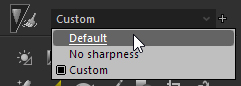 Select a taste from the dropdown list of “Sharpening/Noise reduction”.
4.7.2. Sharpening Adjustment
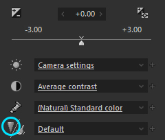 The sharpening adjustment of the software controls the outline phenomenon or noise occurrence mentioned above.
The preset value provides you with well balanced parameters , but you can also set them manually to make more precise adjustments.
Set to an appropriate strength while referring to printed results.
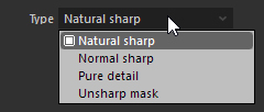 You can select three type of sharpness: “Natural sharp”, “Normal sharp”, “Pure detail” and “Unsharp mask”.
Natural sharp can control false black and white edges that appear near outlines.
An additional feature is that noise in the background is not easily emphasized even with strengthened sharpness.
Normal sharp is ordinary algorism.
Pure detail is an ISL original algorithm for obtaing higher resolution looking images. It gives a stronger effect than with “normal sharp”.
“Unsharp mask” is a process for color space defined only by our company. You can use sharpness while restraining coloring on outlined parts.
4.7.2.1. Natural Sharp
Outline emphasis
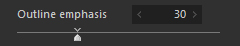 Use it to fix the overall level of the sharpness.
However, brightness changes and false black and white edges becomes more prevalent near outlines when this parameter is high.
Use “Ringing artifact ctrl.” and “Bokeh preservation” to control false black and white edges.Ringing artifact ctrl.
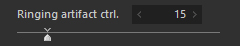 Adjust the strength on false black and white edges that appear around outlines when strengthening sharpness.
However, details may look weak, so adjust “Outline emphasis” and balance while checking.* A “ringing artifact” refers to false black and white edges near outlines.
Bokeh preservation
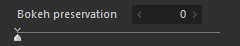 This controls noise that appears when strengthening sharpness and false black and white edges when overemphasized.
However, details may look weak, so adjust “Outline emphasis” and balance while watching.
As the “Ringing artifact ctrl.” has different tendencies in control, it is recommended that if you raise “Bokeh prevention,” you lower “Ringing artifact ctrl.,” and that if you raise “Ringing artifact ctrl.” you lower “Bokeh prevention.”
4.7.2.2. Normal sharp / Pure detail
Outline emphasis
Use it to fix the overall level of the sharpness.
Detail emphasis
 Use it to fix the emphasis level of fine edge (detail).
When increasing this parameter, you can improve resolution of the detail without emphasizing outline.
However, this function emphasizes noise at the same time, remember to balance with noise level.
Use it to fix the emphasis level of fine edge (detail).
When increasing this parameter, you can improve resolution of the detail without emphasizing outline.
However, this function emphasizes noise at the same time, remember to balance with noise level.* Detail emphasis level changes according to both of (1) outline emphasis parameters and this parameter. When decreasing (1) outline emphasis, detail emphasis also becomes smaller at the same time. At first, make rough adjustments by (1) outline emphasis parameter and then adjust accordingly with this parameter.
False outline ctrl.
 Use this to adjust the level to control false black or opposite coloring which appearing around the outline when the sharpness is increased.
However, when this parameter is increased, color separation doesn’t work well (The color in the color boundary between different colors is lost and the area becomes white).
Keep this parameter and the color separation in balance.
Use this to adjust the level to control false black or opposite coloring which appearing around the outline when the sharpness is increased.
However, when this parameter is increased, color separation doesn’t work well (The color in the color boundary between different colors is lost and the area becomes white).
Keep this parameter and the color separation in balance.
4.7.2.3. Unsharp mask
Amount
 You can specify the “Amount” to apply “Unsharp mask”. The larger value makes the stronger sharpness.
Radius
 It sets the thickness of the edge of the outline emphasized.
The larger value makes the thicker edge, and the smaller value makes the thinner edge.
Typically, setting the range between 0.5-1.0 is recommended.Threshold
 If the value is set smaller, the outlines are emphasized regardless of the clearness of the edge. If the value is set larger, only the outlines are emphasized which has clear edge.
You can prevent the emphasis of the noise with this parameter.
Typically it is set to ‘1’. Please adjust this parameter to balance noise and sharpness.
4.7.3. Noise Reduction Adjustment
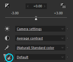 Noise means the rough texture that occurs in high sensitive photography. We call it high frequency noise in the software.
At the high sensitive photography, red, green, or blue spots appear, too. We call them color noise in this software.
The function to remove such noise is the noise reduction.
In this software, the noise reduction function has independent parameters for every category.
The following sections are summaries of the function of noise reduction.
Noise means the rough texture that occurs in high sensitive photography. We call it high frequency noise in the software.
At the high sensitive photography, red, green, or blue spots appear, too. We call them color noise in this software.
The function to remove such noise is the noise reduction.
In this software, the noise reduction function has independent parameters for every category.
The following sections are summaries of the function of noise reduction.
* Noise reduction has been improved in SILKYPIX Developer Studio Pro 6, so if you read development parameters for noise reduction in SILKYPIX Developer Studio Pro 5 or earlier versions, the effects of noise reduction processing will differ from those earlier products.
If development effects are different from what you desire, please readjust on SILKYPIX Developer Studio Pro9 / 9. We apologize for the inconvenience.
4.7.3.1. Color distortion
 The color distortion function changes the process level of color distortion reduction.
The software enables one to reduce both color distortions occur in the fine structure area (high frequency area) and color noise.
The color distortion function changes the process level of color distortion reduction.
The software enables one to reduce both color distortions occur in the fine structure area (high frequency area) and color noise.
When too much color noise at high sensitive photography or color distortions in the fine structure area occurs, increase the reduction level.
However, there are some limitations in this function.
As the reduction level becomes stronger, the color separation level goes down, which makes colors in the color boundary blur. Also, there is a problem of “color spill,” which is the phenomenon that occurs when the vivid color leaks around the picture.
Therefore, too strong reduction level may decrease the picture quality.
4.7.3.2. Fringe reduction
 Fringe reduction adjusts the strength of processing to restrain fringe.
Fringe refers to the phenomenon of purple and green coloring that does not exist in reality on the edges of less bright (dark) portions adjacent to very bright portions.
This kind of coloring can be removed.
4.7.3.3. Neat noise
 This reduces broader noise associated with high sensitive photographs and generates a clean image.
This function reduces two different types of noise.
One is banding noise that runs horizontally or vertically.
If you notice banding noise, strengthen neat noise to adjust so that the banding noise will disappear.
The second are runs of color and brightness brought about by noise.
If you notice runs of color or brightness, further strengthen neat noise and color distortion.
* Neat noise simultaneously performs processing in accordance with strength to remove banding noise and processing to neaten runs of color and brightness.
Strengthening to remove banding noise varies only through neat noise parameters.
Strengthening neatness of runs of color and brightness changes both neat noise parameters and color distortion parameters. (It is determined by the product of these two parameters.)
Therefore, when adjusting neat noise, adjust color distortion at the same time.
If you notice banding noise, first adjust so that it disappears using neat noise, then control runs with color distortion.
If it is running colors and brightness, not banding noise, that you notice, first strengthen color distortion and then adjust neat noise.
When adjusting parameters, it does not matter whether you first do neat noise or color distortion, but it becomes easier to drive parameters by using the above orders.
4.7.3.4. Smoothness
 Use the “Smoothness” slider in the “Noise reduction” sub-control to reduce the high frequency noise. This function reduces the noise, with using RAW data.
The default values for “Color distortion” and “Smoothness” will change depending on the type of camera, ISO film speed, etc.
Please see “4.21.2. Dynamic default” for details.
4.7.3.5. Level of shadow noise reduction
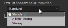 In noise reduction, the level of noise reduction is adjusted differently for bright areas and dark areas of images.
With some objects, however, noise reduction in dark areas may feel insufficient.
This is adjusted with Level of shadow noise reduction.
Level of shadow noise reduction allows you to set whether to increase the level of noise reduction in dark areas for the “Color distortion”, “Fringe reduction”, “Neat noise”, and “Smoothness” adjustment parameters. (*)
If you select “Standard”, noise reduction will be performed at a level equivalent to SILKYPIX Developer Studio Pro 8 and earlier.
If you select “A little strong” or “Strong”, the level of noise reduction in dark areas will be increased.
Details in the dark areas may be lost as a result.
This function is effective when you wish to reduce noise in dark areas, but increasing the level of Smoothness will obscure the entire image.
(This may be seen in images of a night scene.)
Level of shadow noise reduction allows you to adjust only the noise in dark areas.
* If the noise reduction adjustment parameters are not set, changing Level of shadow noise reduction will not result in any changes in the image.
4.7.3.6. Reduce Moiré
 This reduces the moiré that arises in images. Moiré is a pattern that does not actually exist.
You may see moiré in everyday life when watching the news or such, and the announcer is wearing a shirt that is checked or striped. You may be able to see patterns that are not really there.
This is moiré. Many people are probably familiar with this.
Moiré may also occur in photographs taken with digital still cameras.
Moiré can easily occur in photography of minute frequency patterns with an absolute focus.
In addition, it may easily arise in cameras without optical low-pass filters.
Moiré arises in all cameras (sensors), image processing and output devices (monitors, printers, etc.).
This function reduces the moiré that arises in image development.
In addition, this function has an influence on outlines within the image. (Technically, the high frequency response changes.) Outlines may smooth, or conversely, there may be a decrease in definition.
* If you use a camera with an X-Trans CMOS sensor such as FUJIFILM X-Pro1, moiré reduction will already by in effect.
4.8. Development settings
4.8.1. Demosaicing Sharpness Adjustment
 The “Demosaicing sharpness” in the “Development settings” sub-control fixes the development quality.
The default value for “Demosaicing sharpness” changes depending on the type of camera and ISO film speed.
Please see “4.21.2. Dynamic default” for details.
* This cannot be used when JPEG / TIFF is selected.
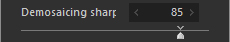 Normally, set this value around “80.”
Set it lower for a picture with full of noise. Please refer to ‘10.1.4. Relationship between Demosaicing Sharpness and Picture Quality’ for more information.
You can change it temporary in order to speed up preview display. Please refer to ‘10.1.1. Speed up Refreshing of Preview’ for your reference.
4.8.2. Resolution Plus
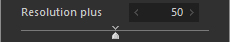 Resolution Plus is a parameter than can be used only if RAF files taken in WIDE mode on FUJIFILM FinePix S3/S5 Pro are developed.
As for the Super CCD honeycomb SRII sensor installed in FinePix S3/S5 Pro, low sensitivity pixels (R pixels) are located between high sensitivity pixels (S pixels).
At our company, we believed that we could raise the limited resolution by using information in low sensitivity pixels.
This software has a development engine that makes constructive use of low sensitivity pixel information in resolution.
However, compared to high sensitivity pixels, low sensitivity pixels have only about 1⁄16 the sensitivity and there is a lot of noise, so when used in resolution, noise may increase and artefacts may be noticeable around the outlines.
This function, Resolution Plus, controls the extent of use of low sensitivity pixels in resolution.
When set to 0, low sensitivity pixel information is not used in resolution (even in this case, it is used as always in gradation reproduction and in high dynamic range processing).
When set to 100, the maximum is used in resolution.
This parameter is influenced by the Demosaicing sharpness settings.
Adjust “Demosaicing sharpness” settings at the same time and balance jags in resolution and the outlines.
* This cannot be used when JPEG / TIFF is selected.
4.8.3. Color space
4.8.3.1. Input color space
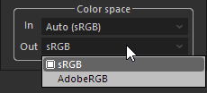 You can specifically set the input color space for a JPEG/TIFF image by this control.
SILKYPIX automatically determines the input color space of a JPEG/TIFF image according to the standard of Exif2.3.
When the JPEG/TIFF image does not include the color space information or when the color space is recorded by other way that is not based on the standard of Exif2.3, SILKYPIX treats the image as sRGB color space.
You can specifically set the input color space for a JPEG/TIFF image by this control.
SILKYPIX automatically determines the input color space of a JPEG/TIFF image according to the standard of Exif2.3.
When the JPEG/TIFF image does not include the color space information or when the color space is recorded by other way that is not based on the standard of Exif2.3, SILKYPIX treats the image as sRGB color space.
Furthermore, if an ICC profile is attached, it will utilize the ICC profile’s color space. (*1)
If an input color space cannot be detected and an input color space is not designated, it will be processed in sRGB.
When SILKYPIX cannot determine the correct color space, it may not be possible achieve correct color reproduction. In this case, please set specifically the input color space by this control.
*1 SILKYPIX performs color management using the OS functions.
Please note that if an ICC profile incompatible with the OS color management system is attached, accurate color reproduction may not be possible.
Please refer to “Determine color space (input color space) of images to be developed” for details.
4.8.3.2. Output color space
Select color space in “Color space” dropdown list in “Color” sub-control to decide the tone expression at development, working color space adjusted by the tone curve, and color space for image file created after development.
You can select “sRGB” or “Adobe RGB”.
sRGB is the standard color space for Windows. Since Windows handles sRGB color space by default, use the software with the sRGB setting generally.
Adobe RGB is effective in processing images which are intended for additional photo retouching software, or for printing purposes.
It has wider color reproduction range than sRGB, but cannot be utilized unless you have proper image processing environment to handle AdobeRGB color profiles (Note that an improper environment will generate strange colors).
When reading files output by Adobe RGB with other software, set Adobe RGB color space for the profile setting (Operation varies depending on each software, so refer to the manual of the software you are using).
This software also enables the embedding of a color profile indicating the color space into an output file. A file with an embedded profile allows transferring the color space to the software supporting the color profile.
In addition, this software complies with Exif 2.3 Specification and outputs Exif information indicating Adobe RGB color space.
Please refer to ‘9.1. File output settings’ for embedding profile or Exif information output.
* When selecting Adobe RGB, the preview is displayed based on Adobe RGB color space. Therefore, when the color management of monitor is not used, colors are displayed inaccurately.
When selecting Adobe RGB, set the color management of monitor to a valid profile so that the correct colors are displayed. Please refer to ‘9.2.1. Color management’.
4.8.4. Develop JPEG/TIFF images
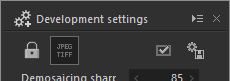 You can switch enable/disable the function to process JPEG/TIFF image.
You can do this with the “Develop JPEG/TIFF images” button or placing a check mark in the “Develop JPEG/TIFF images” box under function settings.
You will not be able to edit JPEG / TIFF images with SILKYPIX if the check is removed (or the button is OFF) from “Develop JPEG/TIFF images”.
In this mode, controls for making adjustments to development parameters are disabled and operations cannot be performed.
Utilize this in the following cases.
When you do not want to make original JPEG / TIFF images subject to editing
If you are someone who always takes photographs in RAW, you can prevent mistakenly making image adjustments to JPEGs recorded at the same time as original images.When you view SILKYPIX development parameters recorded in JPEG / TIFF images
If you select a JPEG / TIFF image developed by SILKYPIX in this mode, you can view the development parameters included in the development results.
The development parameters displayed here are those set when developing the image.
You can copy these development parameters in the paste buffer or storerooms and apply them to other JPEG / TIFF images.
Development parameters will not be displayed if the JPEG / TIFF images were saved under a setting that does not embed the development parameters or if the JPEG / TIFF image was recorded and saved by something other than SILKYPIX.
4.8.5. Develop mark
Set marked development for selected image.
When setting marked development, you can develop a batch of multiple images from [Development (D)]-[Batch develop marked images (B)] in the menu.
4.8.6. Develop
Please see “5.1. Develop” for details.
4.9. Highlight controller
 Highlight controller function controls color creation in highlight area.
The menu command [View (V)]-[Sub-controls]-[Highlight controller] displays the “Highlight controller” sub-control.
This function controls a color clip in the highlight area, where one of color components (R, G, or B) is saturated. There are several types of controls. The “Chroma/Luminance” and the “Saturation/Hue” controls impact on the area where at least one of color components is saturated. The “Luminance restoration” control restores the lightness of the area that were clipped at capture. Combined with under exposure bias adjustment, you can restore gradation to areas that have clipped.
You can restore gradation to areas that have been whiteout.
* “Color reproduction” and “Gradation” has been greatly improved in SILKYPIX Developer Studio Pro 7. Because the developing engine has improved, when reading development parameters for Highlight controller from SILKYPIX Developer Studio Pro 6 or earlier versions, results from Highlight controller processing will differ from earlier products.
If development effects are different from what you desire, please readjust on SILKYPIX Developer Studio Pro9 / 9. We apologize for the inconvenience.
When applying development parameters from earlier versions, icons will be displayed in Thumbnail window and in the status bar.
Please see “3.8. Icons that show status of image” to see if development parameters from previous versions are applicable.
4.9.1. Emphasis on Chroma/Luminance
Chroma/Luminance controls the priority of chroma or luminance to create colors in the highlight area.
The following pictures were developed based on the RAW data with highlight area (flowers). They were developed with chroma, luminance, or intermediate between Saturation/Tone.
Chroma emphasizes the colors of the flowers, and “Luminance” controls the highlight area effectively to emphasize the glare of the reflected light.
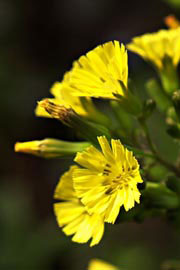
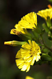
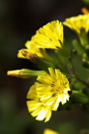
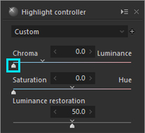
Chroma (value: 0)
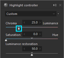
Intermediate (value: 25)
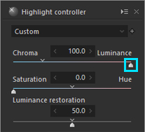
Luminance (value: 100)
Here is another sample.
Highlight controller works effectively with the lighter area such as the sunset scene.
The following pictures, which are sunset scenes, were developed with each priority, chroma, luminance, and intermediate between them.
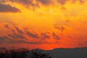
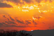
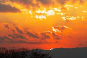
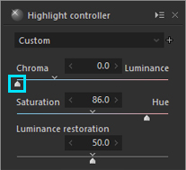
Chroma (value: 0)
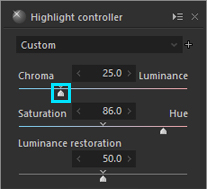
Intermediate (value: 25)
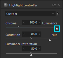
Luminance (value: 100)
4.9.2. Emphasis on Saturation/Hue
After giving priority to chroma with the “Chroma/Luminance” slider, you can also control the priority of saturation or hue to finish development process.
As shown below, since R value (red) of the orange flower in orange was saturated, the hue of the highlight area became yellowish.
In such case, emphasize the hue with the “Saturation/Hue” slider to prevent reversal of the hue.
This process is also effective for the highlight area of skin, which sometimes becomes yellow.
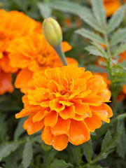

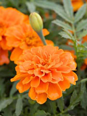
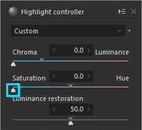
Saturation (value: 0)
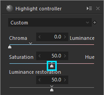
Intermediate (value: 50)
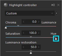
Hue (value: 100)
In some cases, it is more helpful to give priority to saturation.
In the following picture (a bee and a flower), you can see the color of pink and yellow are nicely reproduced by putting priority on saturation.
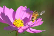
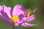
Saturation (value:0)
Intermediate (value: 50)
Hue (value: 100)
4.9.3. Luminance restoration
This function restores original colors, which were lost by over-exposure photography.
In RAW data, the color information may be recorded correctly even though it is lost on the photo.
In such case, make the exposure bias under at the capture stage and you can restore the tones recorded in RAW data.
However, the area where the sensor is saturated cannot be restored with this way. Luminance restoration enables to restore the lost lightness information based on information provided with a sensor with lower sensitivity.
The left is a picture of RAW data, which was taken with exposure set to the trees and ground and developed without exposure bias. The center picture was developed with -2EV exposure bias. The tones of the sky and clouds were restored and you can check lens flare. The right picture was restored by luminance restoration.
As you see, the sky and clouds become clearer with this operation.
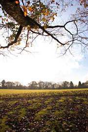
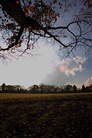
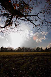
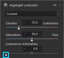
Luminance restoration(value: 0), No Exposure Bias
Luminance restoration(value: 0), Exposure Bias(-2.0)
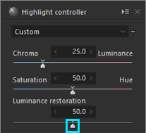
Luminance restoration(value: 128), Exposure Bias(-2.0)
In addition, the following example is created with the image combine of the upper left picture and the sky and clouds in the right picture.
This shows the best result with the restored sky and clouds, and appropriate exposure on the trees and ground. This sample takes full advantage of development based on RAW data.
When you create two types of developed pictures with different exposure bias and luminance restoration parameters, and combine them with a photo-retouching software, you can operate with wide dynamic range and create a better photo. This is the excellent advantage of RAW data.
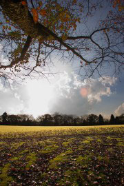
Composite Picture
The example mentioned above is an example that comprised two development results with different exposure bias from photo retouching software. However, there was no trouble in the composition by using dodging adjustments in this software. You can compress and expand dynamic range by using exposure bias on parts of a large photograph with greater differences in brightness.
Please see “4.3.2.1. Dodge / Color Burn / HDR” for details.
4.9.4. Dynamic range
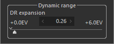 This function allows you to compress the highlight gradation.
If you set it larger value, you can make smooth gradation of highlight area or make detail expression of highlight area.
Areas under moderate brightness will not be influenced.
This compresses and stores RAW data of a wider range in highlighted sections, so the effects are such that gradation of highlighted sections is smoothed and details in highlighted areas are emphasized.
On the other hand, highlighted sections become more moderate.
Please remember that you cannot use this function for overexposed scenes.
If you adjust the “Dynamic range” alone, basically, it will be necessary to leave extra information in highlighted sections.
Decide how much extra information to leave and how effectively it will function. If there is absolutely no room in the highlighted sections there will be no effects even if “Dynamic range” is adjusted.
If the highlighted section has more than 1.0EV space available and “Dynamic range” is set to 1.0EV, highlighted sections are compressed so that values of 1.0EV brightness are expressed as pure white more so than values expressed as pure white to that point.
4.9.4.1. Method for Effectively Utilizing Dynamic Range
In order to effectively utilize dynamic range, you must not lose highlighted parts during photography.
It is also desirable to have as much headroom as possible in the highlighted area when taking a photograph.
The method for taking photographs without losing highlighted portions and with as much headroom as possible depends on the functions of the digital camera that you use.
Generally, photography that does not lose highlighted portions is possible by taking underexposed photographs, but there are cases in which it is hard to lose highlighted portions even when taken with a reasonable exposure using your digital camera.
Using a digital camera with a wide dynamic range is advantageous.
However, no matter how wide the dynamic range of the digital camera photographs is, it makes no difference if it loses the highlighted portion.
Not losing the highlighted portion is the most important condition when taking pictures.
Develop an effective photography method taking into consideration the characteristics of the digital camera you use.
How effective you are when taking an underexposed photograph differs depending on the type of camera you use, its mode, the surrounding environment and the purpose for creating the image. You must pay attention, because taking photographs that are too underexposed leads to increased noise.
As an example, the following explains shooting and developing with a digital single-lens reflex camera with RAW data recorded at 12-bit gradation.
This is a technique for giving attention to the expression of the highlighted parts, so generally, there are many times when the subject is bright enough and it is possible to photograph with an ISO film speed of minimum sensitivity.
Under these type of photography conditions, take underexposed photos decisively at 1.0EV-2.0EV when clipping is a concern for the subject. Keep the ISO film speed as is and take your photographs with your camera’s exposure bias function set to -1.0EV to -2.0EV.
If you correct to a camera exposure bias of -1.0EV and take your photograph, the shutter speed doubles and exposure time is halved.
If you develop this photograph as is, you will end up with a dark photograph under 1.0EV, so sensitize SILKYPIX’s exposure parameter to +1.0EV.
Under these conditions, there are almost no changes if you take your photograph under normal exposure and develop it without sensitization.
One disadvantage of sensitization is that it emphasizes noise, but you cannot tell most of the increase in noise if sensitization is around +1.0EV to +2.0EV with a digital single-lens reflex camera.
This condition means that brightness information will retain 1.0EV better than information projected on the image as development results.
This makes it possible to utilize the space from the highlighted portions and express the highlights.
If photographed at under 1.0EV, the dynamic range parameter functions effectively at 0.0-1.0EV.
If photographed at under 2.0EV, the range of adjustments will increase to 0.0-2.0EV.
* When using FUJIFILM FinePix S3/S5 Pro, gradation to somewhere over 2.0EV is recorded if you photograph in RAW at a setting of dynamic range mode = wide.
* Compared to conventional 12 bit devices, Nikon and Canon 14 bit devices record gradation to somewhere over 0.5EV-1.0EV.
* When RAW photographs are taken with a Canon 14 bit device in a mode that gives priority to high brightness and gradation, gradation is recorded at somewhere over 1.0EV above conventional photography mode.
*1 This depends on the S/N ratio (ratio of image signal to noise) of the photographed image.
This assumes it was photographed at low sensitivity with a digital single-lens reflex camera. If using a small digital camera with an image sensor and taken at high sensitivity, sensitization may be severe.
4.10. Fine Color Controller
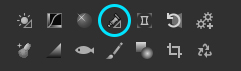 The fine color controller is a powerful color adjusting function that can freely handle colors.
Select [View (V)]-[Sub-controls]-[Fine color controller] from the menu to display the “Fine color controller” sub-control.
It can also be displayed from the fine color controller icon in the sub-control icons at the bottom of parameters controls.
The fine color controller divides colors into 8 hues and provides a function for adjusting colors in each of the hues.
The color circle hue display shown on the control is arranged so that white is in center of the chroma chart, with color positions starting at the 3:00 position on a clock and going clockwise in the following order.
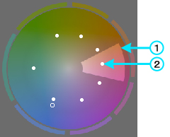
- Color name
- Rose red
- Purple
- Ultra marine blue
- Turquoise
- Blue-green
- Green
- Yellow-green
- Golden yellow
- Rose red
Color placement is arranged on this color circle such that the further from the center of the color circle, the higher the chroma, and they are placed at average color intervals as much as possible to meet human perception.
* A chroma chart of average color differences, called the CIE 1976 UCS Chroma Diagram, is used on the color circle.
There are two main ways to adjust parameters on the fine color controller.
These are a method of operating a mouse on the color circle and a method of setting parameter values using a slider control.
Please use these together for effective parameter adjustments.
4.10.1. Adjustments using the color circle
As seen in the diagram of the color circle shown above, the color circle is divided into 8 hue blocks, and there are operation points in each of these blocks.
(1) shows a block, and (2) shows an operation point.
A hue for operation is selected by clicking any of the 8 blocks.
Borderlines of the blocks of hues for operation are displayed in bold.
Operation points in each block can be moved by dragging the mouse or with the mouse wheel.
With either of these methods, movements along the circumference are interlocked with “Hue,” and distance from the center of the color circle is interlocked with “Chroma.”
Adjusting the “Brightness” parameter can be done with the mouse wheel, but it will not be shown on the color circle.
Parameters adjusted through mouse operations are reflected on the slider control, so both the color circle display and the slider control display are synchronized.
- [Mouse wheel operation]
- You can operate the “saturation” slider with the mouse wheel on color circle GUI.
- [Shift] key + mouse wheel is for the “hue” slider and [Ctrl] key + mouse wheel is for the “lightness” slider.
- You can operate the “saturation” slider with the mouse wheel on color circle GUI.
4.10.2. Adjusting with the sliders
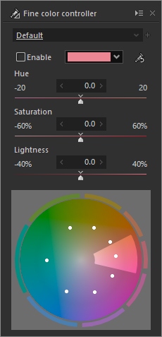 Adjustments to each parameter value on standard controls, compared to the method of adjusting the color circle with the mouse, will be explained here.
Enable checkbox
Enable the fine color control.Hue adjustment
Select a hue for adjustment from the dropdown list.Hue
Set how much change in hue.
Set the angle in counter clockwise rotation from the reference point.Saturation
Set the ratio assuming that the distance from the center of the color circle to the reference point is 100%. When setting -20%, the operation point moves to the inside by 20%, and the saturation level is decreased. When setting 20%, the point moves to the outside by 20% and the saturation level is increased.Lightness
Set the ratio assuming that the lightness of the reference point is 100%. When setting -20%, the lightness level is decreased, and setting 20%, it is increased. (Initialize)
Return all points to the initial state.
4.10.3. Methods and Notes on Utilizing Fine Color Controller
The Fine color controller is a color transformation tool that displays emphasized colors or, conversely, moderates them, and changes colors.
It is advantageous to perform adjustments on the image as the last process because color engineering is a type of image processing that destroys the balance of colors.
We hope that you will experiment and use the various functions, but one matter that requires attention is that it is advantageous to adjust white balance, exposure, color profiles and color representations before adjusting the fine color controller.
White balance and exposure are basic adjustments and giving priority to these adjustments does not mean that you are limiting fine color controller, but if you perform fine color controller adjustments first, you may not be able to adjust the white balance and exposure as you would like.
The color profile and color representation are items you should try adjusting before using the fine controller if you want to emphasize the subject.
It would not be an exaggeration to say that the color profile and color representation are types of fine color controller tastes.
First select a color profile and color representation that seems to be desirable before independently adjusting the fine color controller.
[Example of adjustment] One example would be a photograph of a person as the main subject taken close up against a background of a blue sky and red flowers.
If the sky turns purple under the influence of white balance adjustments so that the person’s skin color is a favorable pink, adjust so that the sky turns into a favorable sky-blue.
- This technique is for adjusting only colors that seem strange such as when a sense of incongruity is born out of the entire photograph due to over emphasizing the main subject by not using the right amount of white balance.
- This technique is for adjusting only colors that seem strange such as when a sense of incongruity is born out of the entire photograph due to over emphasizing the main subject by not using the right amount of white balance.
After appropriately adjusting the white balance, adjust the orange and red so that the person’s skin color will be flattering, and then further adjust so that the blue sky will also be a good color.
- This is a technique for true adjustments of basic correct white balance and adjusting so that the colors you want to emphasize are favored.
- This is a technique for true adjustments of basic correct white balance and adjusting so that the colors you want to emphasize are favored.
Adjust so that the red flowers become pink.
- There may be cases when you do not want to emphasize colors or adjust to a memory color, but rather make adjustments with the effect of changing colors to something different than reality.
- There may be cases when you do not want to emphasize colors or adjust to a memory color, but rather make adjustments with the effect of changing colors to something different than reality.
If red flowers are two bright and there is a whiteout effect, control the whiteout by lowering the red chroma.
- Adjustments with the highlight controller to exposure and saturation will influence not just specific colors, but the entire photograph.
This is an effective method for adjusting only specific colors.
Please see “10.1.5. Adjustment for Over-saturation” for details.
- Adjustments with the highlight controller to exposure and saturation will influence not just specific colors, but the entire photograph.
* If the mouse cursor is over the preview image, the color the mouse cursor is pointing to will be displayed in a circle over the color circle.
Placing the mouse cursor where you want to adjust on the preview image will be an indicator of what color block would be good to adjust.* This parameter category can be turned on / off.
Please see “4.21.1. Setting On / Off” for details.
4.11. Lens Aberration Controller
 Lens aberration controller is a function to correct lens aberration at development in order to create high quality image.
The menu command [View (V)]-[Sub-controls]-[Lens aberration controller] displays the “Lens aberration controller” sub-control. The sub-control can be displayed also with the lens aberration controller button
Lens aberration controller is a function to correct lens aberration at development in order to create high quality image.
The menu command [View (V)]-[Sub-controls]-[Lens aberration controller] displays the “Lens aberration controller” sub-control. The sub-control can be displayed also with the lens aberration controller button under the right.
Photo lenses have aberration. Today, the resolution of digital camera has improved, therefore, lens aberration may have a damaging effect on the picture quality.
There are various kinds of lens aberration such as spherical aberration, coma aberration, astigmatism, curved field, distortion aberration, axial chromatic aberration, chromatic aberration of magnification, and shading reduction that is a decrease of light volume occurring in the periphery.
To adjust these aberration three corrections are available:
shading, distortion, and chromatic aberration.
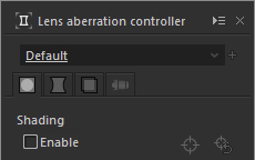 Tabs corresponding to the above three correction functions and the “Lens profile” tab for performing distortion correction using the lens profile are displayed in the “Lens aberration controller” sub-control.
When adjusting each parameter, select either the Shading (peripheral light quantities) ![]() tab, the Distortion
tab, the Distortion ![]() tab, the Chromatic aberration
tab, the Chromatic aberration ![]() tab, or the Lens profile
tab, or the Lens profile ![]() tab.
tab.
4.11.1. Shading (Peripheral Brightness Reduction) Correction
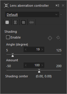 “Shading” corrections contained within the shading
 ![]() tab is a function to correct light falloff at edges, which is a characteristic of a lens, making an area around the object darker. Use two parameters to correct shading.
tab is a function to correct light falloff at edges, which is a characteristic of a lens, making an area around the object darker. Use two parameters to correct shading.
4.11.1.1. Angle of View
 Input the diagonal angle of view of the lens at photographing.
Calculate and correct shading on lens design theory from this angle.
On a lens, light volume is decreasing toward the periphery area. The angle of view is larger in a wide-angle lens and smaller in a telescopic lens.
Based on conversion to 35mm film format (full size digital single-lens reflex camera), the angle of view of a 50mm standard lens is approximately 46 degrees, that of a 135mm telescopic lens is approximately 18 degrees, and that of a 35mm wide-angle lens is approximately 63 degrees. When you input the angle of view,shading correction of a lens is performed through the calculation of logical lens shading.
However, it does not always match to the actual shading of the photograph. (Please refer to ‘4.11.1.3 Detail of Shading Reduction’) Please move the slider and find the best point using the value mentioned above.
4.11.1.2. Correction Ratio for Amount of Light
Input the ratio that you apply for the correction.
When you set the amount 0%, no correction is performed, and the amount 100%, the logical value calculated based on the angle is used. You can set the parameter up to 200%.
You can use this function to adjust the level of correction for the following cases. The case you want to remain the shading effect without complete correction since the shading is one of the tastes that are unique to a lens. Or a case that a bright object is on the periphery of a photo and when you make corrections it becomes too bright and lost.
You can also increase the shading level by setting minus value. Use the value to emphasize the center area on purpose by darkening the periphery, or to make the background quiet.
4.11.1.3. Shading center tool
The cross and circle control is displayed on the preview screen by clicking the ![]() button when the [Enable] box is checked.
button when the [Enable] box is checked.
The location of the cross in the center of the circle indicates the central location of shading effects. You can change the center for correcting shading (peripheral lighting) by dragging this part.
This is useful for obtaining dimming effects equally in the four corners as an effect, even if the center of the angle of view is moved by cropping.
In addition, you can reset the shading central location by clicking the ![]() button.
button.
The central location of the shading effects is the center of the image. Its coordinates are expressed as (0, 0). Each edge of rectangle of the shading effects is expressed as an edge with length 1 based on the edge of the extension area used in the crop tool. Therefore, the extended area for the top left corner is (-0.5, -0.5), the top right corner is (0.5, -0.5), and the bottom right corner is (0.5, 0.5).
In addition, if the shading center is outside the range of the preview display, the control display will turn pink and an arrow indicating the direction of the center will be displayed.
4.11.1.4. Detail of Shading Reduction
Reducing shading happens through several complex factors.
Although image formation is distorted in a wide angle lens, the lens periphery tends to be lighter as the object is much distorted.
For example, fish-eye lens prevents the shading effect by distorting the object in the lens periphery.
On the contrary, with a wide-angle lens, generally, corrections to distortions are performed so that a straight line appears as a straight line, but the perimeter of the image becomes dark because this method corrects by enlarging the perimeter.
Also, in a certain type of lens, a lens aperture seen from an oblique direction becomes smaller (vignetting), and such lens causes larger shading effect in the periphery area than the logical features.
An aperture value also impacts on the shading level. When it is the minimum value, large shading is caused, and when it is a larger value, shading becomes smaller.
Moreover, with a digital camera, oblique incidence to the image sensor causes shading.
Therefore, use the angle of view for reference only. Find the best-balanced point by yourself.
It is helpful to understand that correction amount becomes smaller and correction between the center and periphery becomes linear when making the angle parameter smaller, and correction amount becomes larger especially in the periphery when making the angle parameter bigger.
When you find that most of the area is corrected well, except the periphery area, make the parameter bigger to increase the light level in the periphery. When the relationship between the most of the area and the periphery is less, make the parameter smaller.
4.11.1.5. Color vignetting auto-correction
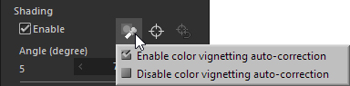 “Color vignetting auto-correction” is a function to correct color vignetting automatically.
“Color vignetting auto-correction” is only available for a photograph taken with a certain camera and recorded in RAW data.
“Color vignetting auto-correction” is a function to correct color vignetting automatically.
“Color vignetting auto-correction” is only available for a photograph taken with a certain camera and recorded in RAW data.
The ![]() icon is shown in the shading tab on the “Lens aberration controller” sub-control when you select a photograph which color vignetting auto-correction can be applied to.
icon is shown in the shading tab on the “Lens aberration controller” sub-control when you select a photograph which color vignetting auto-correction can be applied to.
By clicking the ![]() icon, a context menu to toggle “color vignetting auto-correction” is appeared.
icon, a context menu to toggle “color vignetting auto-correction” is appeared.
Color vignetting is a reduction of brightness or colors at the image corners compared to the image center.
Color vignetting is caused by a difference of receiving angles at the image sensor.
In general, filters to cut infrared (IR) and ultraviolet (UV) are placed in front of the image sensor.
These filters are plate-like glasses with a certain thickness.
An incident luminous flux causes color vignetting.
Brightness or color reductions caused by color vignetting depend on light sources at shooting.
It makes color vignetting difficult to correct.
To correct color vignetting automatically, advanced image processing algorithms are required.
This function corrects color vignetting automatically with our original light sources detection technology.
Our light sources detection technology identifies colors of light sources from a photo taken with your smartphone.
According to identified colors of light sources, SILKYPIX Developer Studio Pro9 / 9 determines correction parameters and corrects color vignetting automatically.
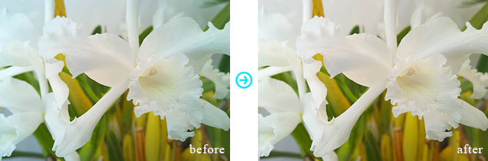
Example of "Auto-correct color vignetting"'
4.11.2. Distortion Correction
“Distortion” corrections contained within the distortion ![]() tab is a function that corrects lens characteristics such as when straight lines turn and are distorted into warps and curves. Before using this function, check the “Enable” checkbox.
tab is a function that corrects lens characteristics such as when straight lines turn and are distorted into warps and curves. Before using this function, check the “Enable” checkbox.
4.11.2.1. Distortion Rate
See the right picture. When the image is distorted like a barrel, move the slider to the left to set minus value. Adjust the parameter with the slider to the point that the distorted line becomes straight. If the image is distorted like a pincushion, shown in the left picture, move the slider to the right to find the best point. If the slider stays at the center 0, no correction is performed. After the correction, you can compare the original image with the corrected image by checking and non-checking the “Distortion” checkbox.
Pincushion Shape
After Correction
Barrel Shape
4.11.2.2. Center/Edge Control
Determine which one should take priority when adjusting distortion, center or edge.
If the image around the center is distorted greatly even though the straight line at the corner is corrected well, move the slider to select the center priority. If the distorted level around the center is too weak, move the slider to an opposite side.
Iterative adjustments of this parameter and distortion rate can correct almost all of the distortion characteristics found in photo lenses. If you use this parameter properly, it is possible to correct or modify a lens having complicated distortion aberration.


Original
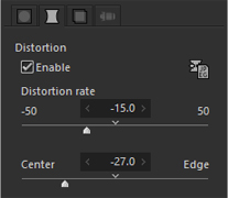
After Correction (Rate: -15)
Most camera lens distortion can be driven to a point where it is not noticeable by alternately repeating these parameter adjustments and adjustments to the distortion rate.
It is possible to correct or mitigate even from a lens with complicated distortion characteristics, such as the so-called jingasa (complex barrel) type, if these parameters are adjusted effectively.
4.11.2.3. Automatic Bias
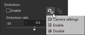 Cameras have an automatic bias function for distortion. Cameras can be set this automatic bias for distortion ON or OFF, and if it can correspond with \var{THISSOFTWARE}, the automatic bias button will be displayed. This setting allows you to change automatic bias later.
If set to “Camera settings” it will perform bias based on the value set on the camera when the photograph was taken.
If set to “Enable” automatic bias will be performed regardless of the value set on the camera when the photograph was taken.
If set to “Disable” automatic bias will not be performed regardless of the value set on the camera when the photograph was taken.
Automatic bias will be performed at the value already set, regardless of the status of checking “ON” for distortion bias on \var{THISSOFTWARE}.
Automatic bias and distortion bias on \var{THISSOFTWARE} is performed separately. If both are ON, both will be performed.
Areas protruded by distortion correction are cropped automatically and are resized to the original image size.
Pixels protruded by distortion correction can be taken out by using the “Extend processing area to entire recorded area” function in the crop tool.
Please also refer to “4.14.4. Extend processing area to entire recorded area”.
Distortion correction functions were developed with the aim to correct lens distortions, but it is possible to use them in various ways, such as alleviating the phenomenon of radial images from wide-angle lens through exaggerated perspective, or on the contrary, strong distortions.
Different from the simple transformation functions in photo retouching software, corrections performed here simulate distortion characteristics that occur with a lens in reference to the design of an actual photographic lens.
The next example is of a transformation from strengthening distortion.
The image before corrections (left side) shows a bubble and face that has been distorted, but the distortion is transformed to a natural form in appearance by making corrections that strongly twist the distortion (right side).
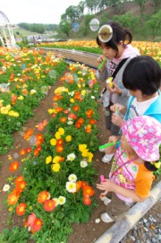
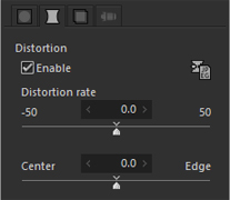
Original
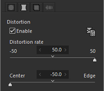
After corrections(Distortion rate: 50, Mid / surrounding stress: -50)
Enjoy combining various parameters that give you the feeling you have a lens that can freely control distortion.
You will surely find new expressions.
4.11.2.4. Automatic distortion correction using JPEG
This function calculates the distortion correction value using the JPEG image recorded when the photograph was taken.
In order to use this function, a JPEG image with distortion corrected must be recorded at the time the photograph is taken.
* This function is effective only for a single selected image.
* This function cannot be used when a JPEG / TIFF image is selected.
For the selected image, when there is a JPEG / TIFF image with the same file name as the RAW image to be corrected, the ![]() button will be activated.
button will be activated.
If you click the ![]() button, the “Automatic distortion correction using JPEG” dialog will be displayed.
button, the “Automatic distortion correction using JPEG” dialog will be displayed.
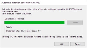 If you click the [Execute] button, the distortion correction values will be calculated.
When the calculation is complete, the results will be displayed.
Click [OK] to reflect the correction values to the “Distortion rate” and “Center/Edge” sliders and perform distortion correction,
This function analyzes the image to be corrected and performs calculations, so the correction results may vary between images photographed under the same shooting conditions using the same camera and lens.
If the aspect ratio, pixel count and angle of view differ between RAW and JPEG images, correction values may not be calculated correctly.
4.11.3. Chromatic aberration
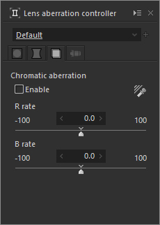 “Chromatic aberration” corrections contained within the Chromatic aberration
 ![]() tab is a function that corrects lens characteristics such as when chromatic aberrations of magnification appear as coloring on the edges around the image.
tab is a function that corrects lens characteristics such as when chromatic aberrations of magnification appear as coloring on the edges around the image.
The transverse chromatic aberration is caused by the difference in lens magnification rates for each colored light (red light, green light, and blue light) incoming to a lens.
The transverse chromatic aberration correction is performed by changing R and B magnification slightly.
First, enlarge the area, where the edge of an object in the image periphery is colored, to more than 400%, and display it.
Then, decrease the color distortion in the “Noise reduction” sub-control (for example, 0 - 80).
After that, check the “Chromatic aberration” checkbox to adjust the R rate and the B rate.
When you correct a picture, enlarge the periphery area as shown below to check the correction result and change parameters.
4.11.3.1. R rate
This adjusts the lens magnification for red light. If the edge is colored by red or cyan (complimentary color of red), change this parameter first.
4.11.3.2. B rate
This adjusts the lens magnification for blue light. If the edge is colored by blue or yellow (complimentary color of blue), change this parameter first.
When these two parameters are appropriate, coloring is decreased most.
First, look the edge condition and change the R rate so that “red <–> cyan” in the both sides of edge is decreased. Then change the B rate to adjust “blue <–> yellow” coloring. Repeat the R rate and B rate adjustments to find the best point.
Do not try to decrease coloring, but try to distribute the edge coloring uniformly. After that, when increasing the “Color distortion” slider in the “Noise reduction” sub-control, the remaining colors are disappeared. Increase the parameter until you are satisfied, and finish adjustments.
At this time, if colors still remain even after the color distortion is maximized, there is a possibility that transverse chromatic aberration is so big that it exceeds the correctable range or that coloring occurs because of aberration other than transverse chromatic aberration. For example, too light background shows a possibility of coma aberration.
At the present time, you can correct transverse chromatic aberration.
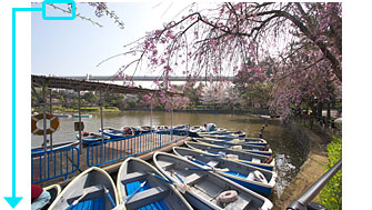
The Original Picture
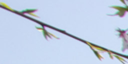
Before Correction
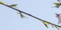
After Correction
4.11.3.3. Chromatic aberration tool
This tool allows you to adjust “R rate” and “B rate” by one action.
Click  button to switch to “Chromatic aberration tool”, and drag the target rectangle area on the preview image.
Then “chromatic aberration” parameter is automatically calculated.
Please retry a few times with another position until you get the good result.
* Please refer to [Reason to enlarge more than 400% and selecting edge for proper correction].
[Reason to enlarge more than 400% and selecting edge for proper correction]
Enlarging preview with more than 400% stops simplified development and glare at the time of updating preview, so you can view images more easily. In transverse chromatic aberration correction process, it is recommended to set the preview ratio with more than 400% in order to check changes in the image and to adjust parameters. If updating preview according to parameter changes is too slow to display, increase the preview ratio more, or make the window for displaying updated preview smaller.
It is preferable to select the edge you want to change when enlarging a display for adjustments. Please pay attention to the following points.Do not select edges in too light (white) background.
The background of the sample is not lost, though, the tone of this picture is light and aberration appears in the twig against the background of the light sky. You should not select the point in such background for aberration correction. The white background is too shiny, and coloring is generated by not only transverse chromatic aberration but also by other aberration such as coma aberration or astigmatism that make difficult to adjust parameters.Select an edge perpendicular to a radial line through the image center if possible.
Transverse chromatic aberration appears because of difference between the magnification for each color. Therefore, it hardly appears on the radial line through the screen center and often appears on the edge perpendicular to a radial line through the screen center. Selecting the edge perpendicular to the radial line makes parameter adjustments easier.Select an edge in the periphery of the target image if possible.
Transverse chromatic aberration impacts most on the periphery of the screen. Coloring is becoming stronger in the area far from the center of the image. Check the edge in the image periphery to make adjustments.
* This parameter category has Enable/Disable setting. Please refer to ‘4.21.1. Setting On / Off’ section.
4.11.4. Lens profile
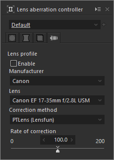 “Lens profile” found in the Lens profile
 ![]() tab is a function for performing automatic distortion correction based on the lens information prepared in advance.
tab is a function for performing automatic distortion correction based on the lens information prepared in advance.
SILKYPIX Developer Studio Pro9 / 9 uses the lens database that comes with Lensfun, an open source library, for lens information.
Please refer to the Lensfun website (English) for details on the Lensfun lens database.
To perform correction using the lens profile, turn ON the “Enable” checkbox.
* This function cannot be used for JPEG / TIFF images.
* To use this function, a dedicated data file must be created in advance from the lens database.
If there is no data file, the controls within the Lens profile tab will be disabled, and this function cannot be used.
Please refer to 4.11.4.5. About create data file for the lens profile for details.* We are unable to respond to questions regarding the Lensfun lens database and lens information. We appreciate your understanding.
Lens profile controls are contained in the “Lens aberration controller” sub-controls, but lens profile parameters are handled independently.
However, the dropdown list of “Lens aberration controller” sub-control tastes and the colors of sub-control icons when parameters are edited will be shared.
Lens profile parameters will not be included when pasting development parameters.
4.11.4.1. Manufacturer
A list of lenses that can use the lens profile will be shown in a dropdown list.
Please select the manufacturer of the lens to which you wish to apply the lens profile.
If the appropriate lens profile could be identified from the Exif information of the RAW data, the manufacturer contained in that lens profile will be set as the default value.
If the appropriate lens profile could not be identified automatically, “Select manufacturer and lens” will be displayed.
The following messages may be displayed in the “Manufacturer” dropdown list.
“Data file does not exist”
This message is displayed when the data file needed to used this function is not found.
If a data file for the lens profile was not created when launching the software, this function cannot be used.
Please refer to “4.11.4.5. About create data file for the lens profile” for information about the data file for the lens profile.“Select manufacturer and lens”
This message is displayed when the appropriate lens profile is not identified automatically from the Exif information of the RAW data.
In this case, you can perform the correction by selecting the manufacturer and lens from the dropdown list.
Please note, however, that the appropriate lens profile may not exist.“This RAW cannot be corrected”
This message is displayed when distortion correction using this function cannot be performed on the selected RAW data.
SILKYPIX Developer Studio Pro9 / 9 always displays optimal development results for some RAW data without using this function.
For this reason, automatic distortion correction using this function cannot be performed on such RAW data.“Cannot use for JPEG/TIFF”
This message is displayed when a JPEG / TIFF image is selected.
This function cannot be used for JPEG / TIFF images.“Correction information not found”
This message is displayed when the same lens profile as the one recorded in the development parameter file is not found.
The applicable lens profile may have been deleted, or its name may have been changed, due to the lens database being updated or for other reasons.
To correctly reproduce the adjustment results, a lens profile based on the same lens database information as the one when the adjustment was performed must be prepared.
While you can select another dropdown list and apply a different lens profile, please note that the information recorded in the development parameter file will be overwritten and lost.
When you cannot use this function, controls within the Lens profile tab will be disabled.
4.11.4.2. Lens
A list of lenses for the selected manufacturer will be displayed in a dropdown list.
Select the lens to which you wish to apply the lens profile.
If the appropriate lens profile could be identified from the Exif information of the RAW data, the lens contained in that lens profile will be set as the default value.
4.11.4.3. Correction method
A list of correction methods available for the profile corresponding to the selected manufacturer and lens will be displayed in a dropdown list.
In many cases, only one method will be displayed, but multiple methods may be available depending on the profile.
If you are presented with multiple correction methods to choose from, select one that is the most suitable for correcting the selected image.
* Correction methods are displayed based on the lens profile information, so we are unable to provide information about how correction methods are selected or other details. We appreciate your understanding.
4.11.4.4. Rate of correction
You can adjust the rate of distortion correction performed based on the lens profile.
4.11.4.5. About create data file for the lens profile
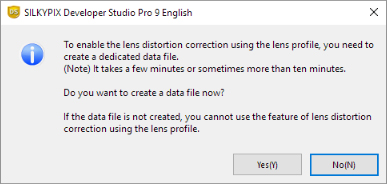 SILKYPIX Developer Studio Pro9 / 9 contains a Lensfun database file. To perform correction processing using the lens profile in a short amount of time, you need to create a dedicated data file in advance from the database.
This data file needs to be created when this software is launched for the first time or when the lens database is updated.
When a data file needs to be created, a message dialog confirming whether to create the file or not will be displayed (*).
If you select “Yes”, the lens database will be converted into a dedicated data file.
The data file will normally be created in a few minutes, but it may take more than 10 minutes depending on your PC environment.
You may skip data file creation by selecting “No” when the message dialog is displayed.
Please note, however, that if the data file does not exist, controls inside the Lens profile tab will be disabled, and this function cannot be used.
* This message dialog is displayed when the “Create data file for the lens profile” checkbox in “Function settings” is turned ON.
When the checkbox is turned OFF, this confirmation message dialog will not be displayed even when a data file needs to be created.
Please refer to “1.3. Create data file for the lens profile” for details.
4.12. Rotation/Shift lens effect
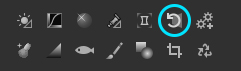 The menu command [View (V)]-[Sub-controls]-[Rotation/Shift lens effect] displays the “Rotation/Shift lens effect” sub-control. The sub-control can be displayed also with the Rotation/Shift lens effect button under the right.
* When you are changing “Rotation/Shift lens effect” parameter, grid is displayed automatically as default setting. (Please refer to ‘9.2.3.3. Grid Settings’)
4.12.1. Rotation
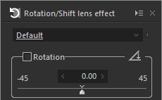 Rotation is a function to rotate an image.
This software allows -45degree to +45degree rotation.
Rotation is a function to rotate an image.
This software allows -45degree to +45degree rotation.
An image is rotated and cropped to the same aspect ratio of the image, and then the rotated image is enlarged to the same size of the image. This procedure helps to keep the number of pixels after a development and prevent to lose a resolution. When a crooked photograph is shoot, rotation function is useful to straighten such photograph.
This software allows large rotations of -45degree to +45degree, but larger areas will be lost with larger rotations.
In this case, you can use “4.14.4. Extend processing area to entire recorded area” function to cut off pixels by displaying all pixels lost through rotation.
4.12.1.1. Rotation tool
Rotation tool can correct a slant horizontal/vertical line to a horizontal or vertical.
You can use this tool on “preview mode” or “combination mode”. You can use the “Rotation tool” by clicking menu command [Tools (T)]-[Rotation tool] or button on the “Rotation/Shift lens effect” sub-control.
Then the mouse cursor shows you “Rotation tool” mode. In this mode, please trace the horizontal line or vertical line by mouse dragging.
Then the rotation angle is set automatically so as to correct the horizontal line or vertical line horizontally or vertically respectively.
4.12.2. Shift lens effect
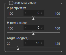 Shift lens effect has advantages such as shift lenses have.
With this function, you can make perspective control, or correct a distorted building to a straight one.
The “V perspective” can change the magnifications for the upper area and lower area of the image. When moving it to the left (smaller value), the magnifications for the upper area becomes larger, and to the right (large value), the magnifications for the lower area becomes larger. The “H perspective” can change magnifications for the left area and the right area of the image. When moving it to the left, the magnification for left area becomes and to the right, the magnification for the right area becomes larger.
The modified image shape becomes a trapezoid or distorted rectangle, however, it is automatically cropped and modified to restore the original shape at the original aspect ratio. Therefore, the number of pixels does not change, avoiding resolution reduction due to deformation.
When you use pixels lost by automatic cropping in shift lens effect, you use Extend processing area to entire recorded area function in the crop tool to display all lost pixels. Then, you crop unnecessary parts of these pixels. In this case, the “extension” of cropping area is used. Please refer to ‘4.14.4. Extend processing area to entire recorded area’.
Shift lens effect can be applied to a wide range of photographs, not just pictures of buildings.
As seen in the following example, you can reduce the size of a face and make legs look longer in pictures of people. This is an example (after corrections) of an image (before corrections) where legs look longer by making the difference in distance look shorter with a shift lens effect of +6 (bottom: fall).
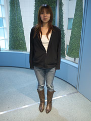
The Original
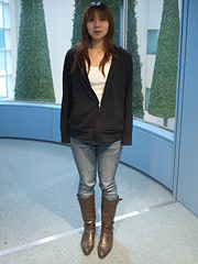
After Correction (V perspective: +6)
The deformation of this process is not a simple conversion from a rectangle to a trapezoid, but the projection conversion from three-dimensional space to two-dimensional space. This is the same type of conversion when taking a picture of real three-dimensional objects with a camera. Then you can get the same effect of using a shift lens.
Using this tool, you have the lens which can shift freely. Try various combinations of parameters to find a new expression.
4.12.2.1. Angle
You will need information on angle of view of a lens in order to get the right effect of shift lens effect.
The default angle-of-view parameter is set almost properly based on the Exif information of the input file.
However, when you don’t attach a manufacturer-made lens or attach an old lens, the angle of view may not be set properly.
If you find that the image is distorted vertically or horizontally after the shift lens effect process, adjust the “angle” parameter.
Frequent use of the “angle” parameter gives an impression as if the aspect ratio with shift lens effect changes.
Enjoy this as a part of the expressions.
* This parameter category can be turned on / off.
Please see “4.21.1. Setting On / Off” for details.
4.13. Effects
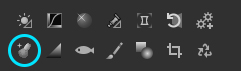 When you select [View (V)]-[Sub-controls]-[Effects] from the menu, the Effects sub-control will be displayed.
It can also be displayed from the  icon in the sub-control icon at the lower right.
4.13.1. Portrait beautification
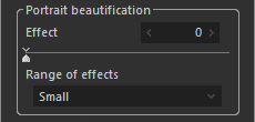 You can control details such as skin chapping and keratin by automatically detecting and smoothing out parts close to the skin color.
Natural, high-resolution process is possible in skin tones and even in other borderline parts.
4.13.1.1. Effect
This adjusts the emphasis of effects to replace skin chapping and keratin with skin tones.
Dark colored blotches on skin can be easily eliminated by raising the effect.
However, as this effect is increased, the texture of skin and hair may appear as if it were painted.
4.13.1.2. Range of effects
This sets the range of effects for portrait beautification processing.
By increasing the range of effects, you can eliminate large blotches that cannot be removed simply by adjusting effect.
However, as the range of effects is increased, portrait beautification effects on smaller blotches will decrease.
Please use a range of effects that meets the blotches you wish to eliminate.
4.13.2. Add noise
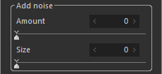 When you select [View (V)]-[Sub-controls]-[Effects] from the menu, the Effects sub-control will be displayed.
4.13.2.1. Amount
You can adjust the strength of added gray scale noise.
Strong settings strengthen the noise contrast, leading to strong noise.
4.13.2.2. Size
You can control the size of gray scale noise.
Consider the final print size through magnifying or shrinking so that you can determine the size of noise based on your usage.
4.13.3. Blurred / Sharp periphery
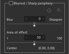 Blurred / Sharp periphery can be used to blur or sharpen the periphery of an image with its center as the reference point.
The blurring and sharpening effects will be stronger farther out from the center.
You can also move the center of the effect.
Turn ON the checkbox to enable Blurred / Sharp periphery.
4.13.3.1. Blurring / Sharpening
Set the strength of the blurring or sharpening effects.
Move the slider farther to the left to make the “Blurring” effect stronger.
Move the slider farther to the right to make the “Sharpening” effect stronger.
Neither effect will apply when the value is 0.
4.13.3.2. Area of effect
Set the area of the blurring or sharpening effect.
Smaller values will only apply the effect farther away from the center.
Larger values will apply the effect closer toward the center.
4.13.3.3. Tool for the center of the blurred / sharp periphery
If you click the ![]() button, a control consisting of a cross and a circle will appear on the preview screen.
button, a control consisting of a cross and a circle will appear on the preview screen.
The place where the cross intersects at the center of the circle indicates the center position of the “Blurred / Sharp periphery” effect, and you can drag this control to move the center of the effect.
You can reset the center position by clicking the ![]() button.
button.
The center position of the Blurred / Sharp periphery effect is represented using coordinates, with the center of the image represented as (0, 0) and the length of each side as 1, using the edges of the area expanded with the Crop tool as a point of reference. Accordingly, the top left corner of the expanded area is represented as (-0.5, -0.5), the top right corner as (0.5, -0.5), and the bottom right corner as (0.5, 0.5).
When the center of the Blurred / Sharp periphery effect is outside the range of the preview mode, the color of the control will change to pink, and an arrow pointing toward the center will be displayed.
4.14. Crop tool
 Use to create your work by cropping a part of an image in the photograph.
Cropping can be performed by switching tool mode in the preview display to Crop tool.
The “Crop tool” can be used only if the Preview window is displayed from either Preview display mode or Combination display mode.
Switching to tool mode can be performed by selecting [Tools (T)]-[Crop tool] from the menu, or by clicking on the  icon in the sub-control icon, or by pushing [Ctrl] + [T].
When tool mode changes to “Crop tool”, the Crop tool sub-control will be displayed along with handles for controlling the frame lines that show the cropping area on the preview image.
 When the image is cropped, a cropping mark will be displayed on the thumbnail.
To crop the image, first you can determine a cropping method from the Cropping method dropdown list.
You can freely crop the image, and can crop in accordance with the purpose of the output by fixing the aspect ratio.
There are three way to crop the image: Adjusting a handle displayed in the Preview window with your mouse; Adjusting parameters in the Crop tool sub-control; and dragging on the Preview window.
The cropping area has to be set for each image, but the Cropping method is common to each image as software settings.
4.14.1. How to Operate a Handle in Cropping Area
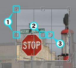 Cropping area can be set by using the mouse to operate handles displayed on the preview image.
Set the area with each handle at every corner and every side.
Move the area with the center handle.
The cropping area is rotated 90 degrees when the rotation handle to the right of center is clicked.
* The cropping area is automatically adjusted so that the aspect ratio is always constant, except for when Cropping method is set to “Custom”.
4.14.2. How to Operate Crop Tool
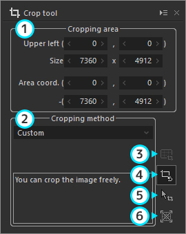
Cropping area
Set a numerical value for the cropping area.Upper left coordinates (x,y)
(B) Size (width x height)
(C) One coordinates (x,y) for the area
(D) The other coordinates (x,y) for the area
Cropping method
Select a method to crop the image.
Select from “Custom”, “Constrain original proportion”, “Specify aspect ratio”, “Print size”, and “Fixed size (fixed aspect ratio)”.Custom
Designate when freely cropping the image.Constrain original proportion
Crop while maintaining the aspect ratio of the original image.
Designate when cropped image and original image share the same aspect ratio.Specify aspect ratio
Designate when cropping to your own set aspect ratio.- (Set output size)
When this setting is on, the numerical value of the aspect ratio set here is the default pixel size at the time of “Develop”.
For example, if cropping is set here to 640:480, whatever value the size of the actual cropping, the default pixel size at the time of “Develop” will be set to 640x480.
Enable this when the output pixel size is set and cropping will match it.
- (Set output size)
Print size
Crop to the aspect ratio of the printing area for the currently set printing paper.
Use this so there will not be any wasted space when printing.
When designating this setting format, you must first complete printer settings.Fixed size
Crop to an aspect ratio of a standard size found on the list.
 Apply specified aspect ratio
Automatically crop the image with the selected cropping method.
If the aspect ratio is set, it crops to the designated aspect ratio. Initialize to default
Set cropping area to the initial area. Crop image on preview
Crop the image by dragging the mouse on the preview window. Extend processing area to entire recorded area
Extend so that you can designate all areas recorded in RAW data as subject to processing.
4.14.3. Crop image on preview
Click the icon to switch to crop the image by dragging the mouse on the preview window.
Set a rectangle from the start point of the drag to the end point as the cropping area, following the Cropping method.
The rectangle from the start point of the drag to the end point will be the cropping area when Custom is selected as the Cropping method.
When other settings are selected, the aspect ratio of the cropping area is fixed.
The rectangle cropping area is automatically calculated and displayed from the location of the mouse while dragging.
4.14.4. Extend processing area to entire recorded area
With RAW data, information on an area a little larger than the area for development processing may be recorded as a photograph through default development processing.
This area is called the extension area.
Also, whiteout areas caused by “Distortion” from “Rotation/Shift lens effect” and “Lens aberration controller” are included in the extension area.
When Extend processing area to entire recorded area is on, the cropping area, including this extension area, can be set.
The size of extension areas varies according to the type of digital camera.
Also, black areas from no exposure and invalid images such as electronic noise may be recorded, depending on the type of camera.
Blank areas that occur as a result of edited parameters are processed in gray.
4.14.5. How to handle the RAW data with the aspect ratio set on a camera
There are two types of RAW data with the aspect ratio set on a camera. One is the RAW data that only contains image data in the certain area cropped in accordance with the aspect ratio, and the other one is the RAW data that contains all image data of the camera and the aspect ratio as EXIF information.
When you develop the latter RAW data, the developed image is cropped in accordance with the aspect ratio in one of the following ways.
Adjust the area for development processing in accordance with the aspect ratio
The area for development processing is adjusted in accordance with the aspect ratio.
The rest of the area of RAW data is considered as the extension area. So you may use the rest of the area by clicking “Extend processing area to entire recorded area.”Adjust the initial cropping area of a developed image in accordance with the aspect ratio
The initial cropping area of a developed image is adjusted in accordance with the aspect ratio.
The image area for development processing is the same with the area of the RAW data that does not contain the aspect ratio.
This function is only available for RAW data taken with a certain camera. When this function is unavailable, the aspect ratio is ignored and RAW data is developed with the same area of RAW data that does not contain the aspect ratio.
4.15. Monochrome controller
 With the Monochrome controller, images are converted in black and white using two kinds of settings. You can make adjustments by using the “Color Filter” simulates the effect of designating a color filter on a lens, and “Lightness” adjusts the brightness of a specific hue.
Select [View (V)] - [Sub-controls] - [Monochrome controller] to bring up the Monochrome controller. You can also bring it up with the  icon among the sub-control icons at the lower right.
If the Taste drop down list is set to “Default,” you can return to the status just before starting operations with the Monochrome controller.
4.15.1. Color Filter
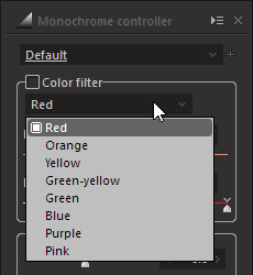 Color filters simulate situations when filters of the colors selected from the pull down list are attached to the camera.
First, select the hue name of the filter from the following eight (8) colors using the pull down list. Adjust the selected filter with “Hue” and “Depth.”
- Hue name
- Red
- Orange
- Yellow
- Green-yellow
- Green
- Blue
- Purple
- Pink
- Red
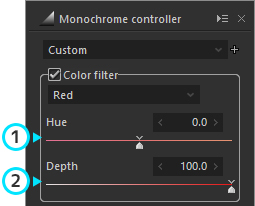
Hue
Adjust using the slider from “-5.0” to “5.0.”
Correct the filter hues to be simulated.Depth
Adjust using the slider from “10.0” to “100.0.”
Adjusting towards “100.00” will result in a status with darker filters attached.
4.15.2. Lightness
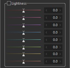 Adjust the lightness of various hues using the slider from “-50.0” to “50.0.”
Adjusting to “-50.0” becomes darker and adjusting towards “50.0” becomes brighter.
- Hue name
- Red
- Purple
- Ultra marine blue
- Turquiose
- Blue-green
- Green
- Yellow
- Orange
- Red
4.15.3. Develop as monochrome
 Operations can be made by enabling the Color Filter or lightness on the Monochrome controller.
If you operate the Monochrome controller when a check mark is on this item, immediately after starting operations the image becomes black and white and processes will be reflected on the image.
After selecting a hue with the Color Filter, by using the Monochrome controller with this item disabled, you can apply the selected hue to the image and process it.
In addition, if you do not select a Color Filter and perform operations of the Monochrome controller with this item disabled, the image will reflect processing without Black and White.
4.16. Underwater photo controller
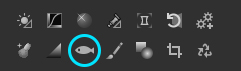 With the Underwater photo controller, you can make special adjustments for underwater photography, such as white balance dedicated to underwater photographs and color restoration to restore colors lost in the water.
The Underwater photo controller will be displayed by selecting [View (V)] - [Sub-controls] - [Underwater photo controller] from the Menu.
You can also have it displayed by selecting the [Underwater photo controller] icon from among the Sub-control icons at the bottom of Parameter Controls.
4.16.1. Auto White balance for underwater photo
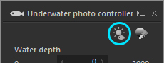 By clicking on the
  button, the image will be analyzed, white balance will automatically run so as to remove blueness from the underwater photograph, and the color temperature and Color deflection, as well as the Water depth and Color deflection (underwater) will be set.
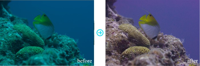
4.16.2. Gray balance tool for underwater photo
With the Gray balance tool for underwater photo, you can designate the portions to be expressed in gray (achromatic color) within the photograph, and it will automatically adjust the white balance and calculate the color depth and underwater color deviation in order to express those portions in gray.
Click the button to enter the white balance adjustment mode using the “Gray balance tool for underwater photo”.
This is an especially effective method when white objects (or objects with no color or achromatic color) are shown in the picture.
Even if not completely white, you can drive this by using the color depth and underwater color deviation after using rough white balance by clicking on sandy areas or such.
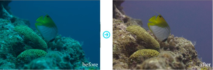
4.16.3. Water depth
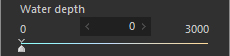 With Water depth, you can adjust the white balance corresponding to the water depth.
Use the slider to adjust from “0” to “3000.”
The higher the number, less blue and more red will be emphasized.
4.16.4. Color deflection (unferwater)
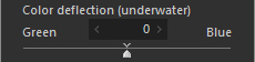 Color deflection (unferwater) adjust greens and blues in images depending on the color of the water.
Use the slider to adjust from “Green (-100)” to “Blue (100).”
When shooting in water that is highly transparent, blues in the image will be emphasized.
In this case, white balance can be done by adjusting the Color deflection (underwater) to the green side.
Also, in the case of muddy waters, the image will be greenish.
In this case, white balance be done by adjusting the Color deflection (underwater) to the blue side.
4.16.5. Color restoration
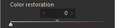 With Color restoration, you can adjust the amount of restoration of reds, as well as other color changes that are lost in the water due to this.
Use the slider to adjust from “0” to “200.”
When set to “0,” Color restoration will be performed.
This is a color reproduction that is almost similar to the color actually perceived by the diver, and uses only white balance.
When set to “100,” the amount of color restoration computed by the program is applied 100%, and attempts to restore colors to underwater objects such as fish when seen from the surface of the water.
4.16.6. Muddy reduction
 This is a function to eliminate light scattering due to turbidity in the water.
Use the slider to adjust from “0” to “100.”
If you increase the amount of Muddy reduction, the image becomes darker.
This is because the light scattered by turbidity is removed.
If the image becomes too dark, adjust the brightness by using Exposure Compensation in conjunction with this function.
4.17. Spotting tools
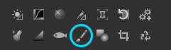 Spotting tools are tools for erasing dust and such found in photographs and correcting for red eye.
The main purpose is for making corrections when dust is found on the photograph or for removing dust from images made from film scanners or red eye from flashes.
To use spotting tools, either select [Tools (T)]-[Spotting tools] from the menu or switch to “Spotting tools” mode from  on the sub-control icon when in the preview display.
A “Spotting tools” sub-control will be displayed when you switch to “Spotting tools” mode.
Also, a navigation display will appear for the “Spotting tools” display area on the preview display.
4.17.1. How to Erase Spots
Two methods to erase dust are included in “Spotting tools”: “Auto Erase” mode and “Copy” mode.
“Auto Erase” mode automatically erases spots by clicking on the area with spots.
“Copy” mode hides spots by copying designated areas on top of spots.
You can also remove corrections to spots in the “Eraser” mode.
You can combine these two methods.
If you are not able to completely erase in “Auto Erase” mode or if you can see traces of the erasures, you can make additional corrections in the “Copy” mode.
You can also make more natural finishes by using the “Eraser”.
4.17.2. Red Eye Correction
The “Red Eye Correction” mode effectively corrects for red eye from surrounding hues by clicking on the area including the whole iris.
If the clicked area falls on a previously clicked area for red eye correction, the previous correction is cancelled and the new area will be used for processing the correction.
In addition, you can cancel corrections with the “Eraser” mode.
4.17.3. Operation Methods
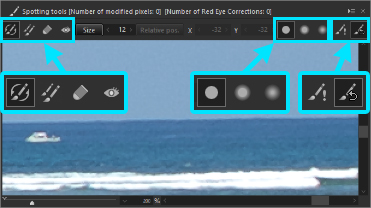 Each of the four operation modes, “Auto Erase”, “Copy”, “Eraser” and “Red Eye Correction”, are performed by left clicking the mouse over the “Spotting tools” sub-control preview display, and in the area inside the circle cursor in each mode.
You can remove dust and make red eye corrections by switching to operation mode and adjusting the size of the circle cursor.
[Operating Mode]
 : Auto Erase
 : Copy
 : Eraser
 : Red eye correction
[Tool effects]
 : Wide pen
 : Medium pen
 : Thin pen
[Other Functions]
 : Emphasize spotting areas
 : Initialize spotting areas
4.17.3.1. Operation Modes
You can switch between the four modes, “Auto Erase”, “Copy”, “Eraser” and “Red Eye Correction”, while doing your work.
Switch operation modes using the , , and ![]() icons.
icons.
4.17.3.2. Tool effects
The effects of each tool, “Auto Erase”, “Copy” and “Eraser”, take place within the area shown in the circle cursor.
The effects of these tools are stronger in the center of the circle cursor and weaker near the edges, but you can choose from three degrees of strength.
Switch “Tool effects” using the , and icons.
However, you cannot select tool effects in “Red eye correction” mode.
4.17.3.3. Emphasize Spotting Areas
Emphasize the display of the area to which corrections were added to the image with “Spotting tools”.
Turn the emphasis display ON / OFF by clicking on .
Areas processed under “Auto Erase” or “Copy” mode are emphasized in red, while areas processed in “Red Eye Correction” mode are emphasized in green.
4.17.3.4. Initialize Spotting Areas
Initialize the “Spotting tools” parameters by clicking on .
Initialized parameters are different depending on the operation mode.
When in “Auto Erase” or “Copy” mode, dust removal parameters are initialized, and when in “Red Eye Correction” mode, red eye correction parameters are initialized.
When in “Eraser” mode, parameters for both dust removal and red eye corrections are initialized.
4.17.3.5. Adjusting Correction Size
All four operation modes, “Auto Erase”, “Copy”, “Eraser” and “Red Eye Correction”, display the area for corrections as the area within the circle cursor.
The area surrounded by the circle cursor is the range of corrections.
Adjust the area of correction for each operation by adjusting the size of the circle cursor.
The size of the circle cursor is designated by displaying “Size” and setting the pixel unit.
In you are in “Copy” mode, you can also change the area to be copied.
The relationship between the area to be copied and the copy location is shown in “Relative position” and you can set the pixel unit.
You can set and change “Size” and “Relative position” through three methods.
Change the displayed numerical value
You can change the displayed numerical value of the “Size” and “Relative position” by adjusting with the spinner or by directly entering in the text box.Change in the “Change size / relative position” mode
Enter the “Change size / relative position” mode by clicking either the “Size” button or “Relative position” button, or by right clicking.
You can change the “Size” by either dragging the edge of the circle cursor or with the mouse wheel, and the “Relative position” by dragging the center of the circle cursor with the mouse.Change by using the [Ctrl] key + mouse
You can adjust the “Size” by holding down the [Ctrl] key and turning the mouse wheel.
Also, if you are in “Copy” mode, you can change the “Relative position” by holding down the [Ctrl] key and moving the mouse.
Once you are used to these methods, you can quickly change the “Size” and “Relative Position.”
4.17.3.6. Changing Display Location / Magnification
The “Spotting tools” preview display can be displayed from 100%-1600% display magnification.
Change controls on the “Spotting tools” sub-control
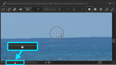 Magnification changes are adjusted with the display magnification slider control.
Display magnification cannot go below 100%.
Adjust display magnification with the scroll bar.
Change the preview window’s navigation display
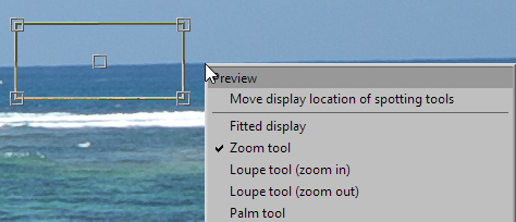 Navigation display showing the area of the “Spotting tools” is executed on the preview window displaying the preview image of the selected image.
You can adjust the display area by moving the handles on the four corners of the navigation frame and with the center handle.
You can also move the display area of the “Spotting tools” to the location of the mouse pointer on the preview window.
Display the context menu by right clicking and select “Move display location of spotting tools”.
Change with [Alt] key + mouse operations
You can change the display location and magnification of the “Spotting tools” preview image with the “Zoom Tool” while holding down the [Alt] key.
You can change the display location with [Alt] key + dragging and resize the display with [Alt] key + [Shift] key + dragging.
You can efficiently proceed with your work by arranging the preview window display when using “Spotting tools”.
4.17.4. Notes
Data to which dust is removed or red eye is corrected using “Spotting tools” is saved as development parameters.
The quantity of this data changes depending on the number of corrections made by “Spotting tools”, but at 10KB-1MB or more, please note that it is quite a large size of data compared to other data.
Correction data from “Spotting tools” cannot be applied with “Paste development parameters”.
Use the “Partial paste of development parameters” function and explicitly designate a “Spotting tools” category.
“Spotting tools” data is recorded and saved in automatically saved development parameters and in development parameters explicitly saved with “Save Development Parameters”, but they are not recorded and saved in development parameters embedded as JPEG / TIFF Exif information.
4.18. Partial correction tool
 The Partial correction tool is a tool for designating areas to be corrected and for making corrections to parts such as shading and contrast within the area.
The main purpose is for making corrections on parts of images, such as raising brightness on expressions on some subjects darkened by backlighting, or for fine tuning the white balance on some subjects seeming to be to bright from reflected light.
To use the partial correction tool, either select [Tools (T)] - [Partial correction tool] from the menu, or switch to “Partial correction tool” mode with  on the sub-control icon.
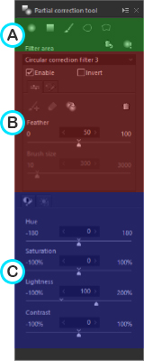 The “Partial correction tool” sub-control will be displayed when you switch to “Partial correction tool” mode.
The “Partial correction tool” sub-control is mainly divided into the following three sections.
(A) Add filter area and operate entire filter area
Add a new filter area and operate all added filter areas.
When performing correction, first add a filter area from here.(B) Operate “area” of selected filter
Set Feather, Brush size, and other parameters when adding a new filter area.
Also, operate each added filter area.(C) Operate “adjustment parameters” of selected filter
Set Lightness, Contrast, and other adjustment parameters for the selected filter area.
* The position of the filter area created with the “Partial correction tool” does not follow the transformations and rotations of the image performed by the “Lens aberration controller” and “Rotation/Shift lens effect.”
Please use the “Partial correction tool” after the adjustment of these parameters.
4.18.1. “Partial correction tool” sub-control functions
4.18.1.1. Add filter area
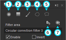 In “Partial correction tool”, you can add five types of filter area: circular correction filter, gradual correction filter, brush area, curve area, and polygon area.
Use a filter area that is easy to use according to the shape of the area that you wish to correct.
- (1) Add circular correction filter
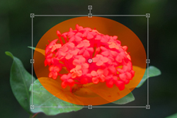 Enter the “Add circular correction filter” mode.
The “Add circular correction filter” mode reflects the results of settings for each item in the “Partial correction tool” sub-control in a circle from the center of the designated area.
After clicking , you can drag across the preview image to designate the area for correction.
Please refer to “4.18.2.1. Circular correction filter” for information about how to operate the “Add circular correction filter” mode.
- (2) Add gradual correction filter
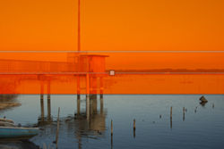 Enter the “Add gradual correction filter” mode.
The “Add gradual correction filter” mode displays a band on top of the image and reflects the results of settings for each item in the “Partial correction tool” sub-control in that band.
After clicking , three bands will be displayed on the preview image.
The range of effects in the gradation state are displayed within the band.
Please refer to “4.18.2.2. Gradual correction filter” for information about how to opeate the “Add gradual correction filter” mode.
(3) Add new brush
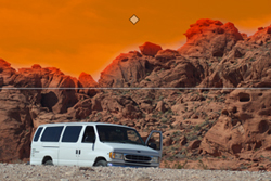 The “Add new brush” mode reflects effects set by the various items in the “Partial correction tool” sub-control for the area you draw on your own by dragging the mouse.
When you click on , a double circle will replace the cursor on the preview image.
The tracks of the brush will be drawn in red on the preview image when you drag the area to be corrected.
After releasing the mouse, the brush area to be effected in accordance with the tracks drawn by the brush will be created.
Please refer to “4.18.2.3.1. Add new brush” for information about how to operate the “Add new brush” mode.* When adding a brush area, set “Feather” and “Brush size” in advance according to the areas you wish to correct.
You cannot change “Feather” and “Brush size” settings once you have drawn with the brush.(4) Add curve
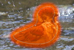 Enter the “Add curve” mode.
The “Add curve” mode reflects effects set by the items in the “Partial correction tool” sub-control for the curve linking the specified points.
If you click , the mouse cursor on the preview screen will change to the “Add curve” cursor
  .
.
Points will be set by clicking on the preview, and a curve linking the points will be displayed.
The curve area will be confirmed by double-clicking the mouse, and effects will apply to the set curve area.(*1)
Please refer to “4.18.2.4. Curve-polygon area” for information about how to operate the “Add curve” mode.
(5) Add polygon
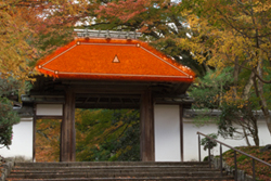 Enter the “Add polygon” mode.
The “Add polygon” mode reflects effects set by the items in the “Partial correction tool” sub-control for the polygon linking the specified points.
If you click , the mouse cursor on the preview screen will change to the “Add polygon” cursor
  .
.
Points will be set by clicking on the preview, and a polygon linking the points will be displayed.
The polygon area will be confirmed by double-clicking the mouse, and effects will apply to the set polygon area.(*1)
Please refer to “4.18.2.4. Curve-polygon area” for information about how to operate the “Add polygon” mode.*1 Curve and polygon areas cannot be set in a way in which sides intersect.
If there are intersecting sides when points are added, the color of the curve or polygon will change to pink, so make sure there are no intersecting sides when confirming the area.(6) Delete all filter areas
By clicking , all items that had been added to the “Filter area” will be deleted.
(7) Emphasize partial correction filter areas
The area where corrections were added to the image with the “Partial correction tool” is highlighted.
You can switch the highlight ON or OFF by clicking on .
.
4.18.1.2. Operate selected filter
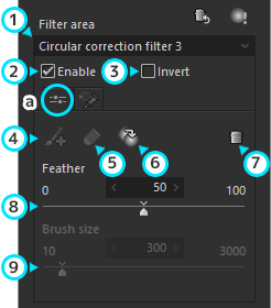 Operate and manage the selected filter area.
For brush areas, set “Feather” and “Brush size” before drawing with the brush.
(1) Filter area
The added filter area will be displayed.
The filter selected here will be the area that can be operated at that time.(2) Enable
This activates the effects of filters selected in the “Filter area.”
The selected effects will be removed if you remove the check mark.(3) Invert
The area where effects are applied and area where effects are not applied will be inverted in the filter selected in the “Filter area”.a. “Basic tools” tab
(4) Add brush to the selected filter area
When you click on , the brush area selected as the “Filter area” will turn into Edit mode, and you can add a brush and draw with it. (*1)
(5) Brush eraser
When you click on , the brush area selected as the “Filter area” will turn into Edit mode, and you can erase the brush you had drawn. (*1)
(6) Duplicate selected filter area
When you click the , it will duplicate the filter that is selected in “Filter area”.
The filter is duplicated under conditions saved for filter size and each parameter in a location a little to the lower right from the filter center of the original.(7) Delete selected filter area
By clicking , only filters selected in the “Filter area” at that time will be deleted.
(8) Feather
Adjust from “0” to “100” with the slider.
You can adjust the shading degree on the borders of the designated area. (*2)
By increasing the value of “Feather”, the shading increases and the effects taper off from the outside to the center.
Conversely, by decreasing the value of “Feather”, there will be less shading and the boundary lines of the designated area appear more clearly.(9) Brush size
This can be set with the slider from “10” to “3000.”
When drawing with a brush under “Add new brush,” “Add brush to the selected filter area,” or “Brush eraser,” you can adjust the size of the brush being drawn with.
Set according to the area to be corrected.*1 This can be used when the filter selected in “Filter area” is the “Brush area.”
*2 When used in the “Brush area,” set before drawing with the brush. You can not change the feathering after drawing with the brush.
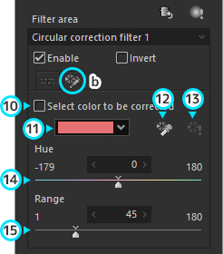
b. “Select color to be corrected” tab
(10) Select color to be corrected
Set whether to enable the “Select color to be corrected” function.
“Select color to be corrected” is a function that can specify a certain color to be corrected within a set filter area.
For example, you can increase the lightness of only red within the area drawn with the brush, and decrease the saturation of only blue within the area where gradual correction filter is applied.
Place a check here to enable the “Select color to be corrected” function.(11) Select color
Select a color to be corrected from the dropdown list.
If you wish to set an approximate color, select one from the dropdown list.
Colors set with the “Color selection tool” or “Hue” slider will be displayed in the dropdown list.(12) Color selection tool
This is a tool for directly specifying a color to be corrected on a preview image.
You can enter the “Color selection tool” mode by clicking .
.
If you specify an area by clicking or dragging over the preview of a selected image, the average color of that area will be set as the color.(13) Preview of selected color
Reflect the selected color on the preview image.
Color will be maintained only in the areas corresponding to the selected color within the filter area, and all other areas will be displayed in monochrome.
Click to turn ON or OFF the preview.
(14) Hue
Set the hue of the color to be corrected with a slider.(15) Range
Using a slider, set the range of the color to be corrected where the color set with the “Hue” slider is the center.
Reducing the range will narrow the range of the color to be corrected, and increasing the range will widen the range of the color to be corrected.
Set an appropriate range while using “Preview of selected color”.
4.18.1.3. Parameters Available for Adjustment
Indicate parameters that can be used to adjust the selected filter area.
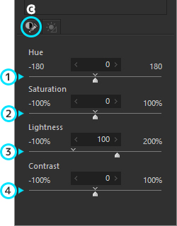
c. “Color / Contrast” tab
(1) Hue
You can adjust from “-180” to “180” with the slider.
This changes the relative hues within the designated area.(2) Saturation
You can adjust from “-100%” to “100%” with the slider.
The higher the chroma, the more brilliant the colors appear, but if the colors are already brilliant, they may become saturated and you may lose details.
When adjusting chroma, check the overall vividness of the colors. It is necessary to adjust so that the vividly colored parts are not saturated and details are not lost.(3) Lightness
You can adjust from “-100%” to “200%” with the slider.
The default value of lightness is 100%. Lightness decreases as this value lowers.(4) Contrast
You can adjust from “-100%” to “100%” with the slider.
Contrast means the difference between bright area and dark area.
When increasing the contrast, the bright area becomes brighter and the dark area becomes darker, i.e. high contrast.
On the contrary, when decreasing the contrast, difference between the bright area and dark area becomes smaller, i.e. low contrast.
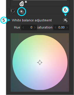
d. “White Balance Adjustment” tab
(5) White Balance Adjustment
You can set the white balance visually by clicking a mouse directly.
You can also adjust white balance in detail by numerical value.* “White balance target” control is based on the accurate color space.
(6) Initialize white balance target
Click to set white balance target to the default value.
4.18.2. How to operate in Filter area mode
4.18.2.1. Circular correction filter
Open the “Partial correction tool” sub-control and click the
.Drag on the part of the image you wish to create to designate a rectangular area.
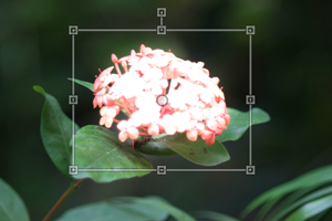
When you designate the area of the first circular correction filter, this becomes “Circular correction filter 1” and an item for this area is added to the “Filter area.”
The designated area has a quadrilateral with a handle. Control the handles by dragging them and fine tuning the area.
Operate the handles by dragging them and fine tuning the area.[How to operate the handles]
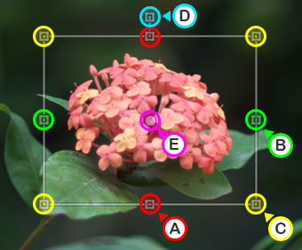
(A) You can adjust the rectangular height, by dragging the handles at the centers in the up and down sides of the rectangle moving to the up or down.
(B) You can adjust the rectangular width, by dragging the handles at the centers in the left and right sides of the rectangle moving to the left or right.
(C) You can expand or reduce the size of the rectangle, by dragging the handles at the corners of the rectangle inside and outside of the rectangle.
(D) You can rotate the rectangle and adjust its angle by dragging the handle projecting out of the top side of the rectangle.
In addition, you can rotate the rectangle 45 degrees by dragging this handle while holding down the [Shift] key.(E) You can move the location of the rectangle by dragging the handle at the center of the rectangle.
After designating the area, control each item in the “Partial correction tool” sub-control and make corrections.
If you want to make adjustments to another area, follow steps (1)~(4) making a new area for a circular correction filter.
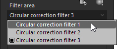 By repeating steps (1)~(4), a new area will be added to the “Filter area” as follows: “Circular correction filter 2,” “Circular correction filter 3,” etc.
* You can control areas one by one on the image.
Therefore, when you have multiple designated areas, you can perform operations by switching areas of operation in the “Filter area.”
4.18.2.2. Gradual correction filter
Open the “partial correction tool” sub-control and click on
.Then, a band from three lines is displayed as operation areas in the center of the image. This becomes “Gradual correction filter 1” and an item for this band is added to the the “Filter area.”
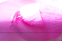
Using the middle line displayed (iii) as a standard, gradation effects become stronger from the lower line (ii) to the upper line (i).
Effects set by the “Partial correction tool” sub-control in each item are applied from line (i) to the upper edge of the image.
Conversely, it does not take effect from line (ii) to the lower edge of the image.- [How to operate bands]
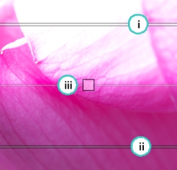 The mouse pointer is replaced with
  when it is over the handle at the top of the central line.
You can move the center of the band up or down by dragging up or down when the band is horizontal.
You can move the center of the band left or right by dragging left or right when the band is vertical.
The mouse pointer is switched to when you point it to any location on the central line, except for on handle (iii).
You can rotate the area by dragging in this state.
You can move the location of the band by dragging handle (iii) on the central line.
- [How to operate bands]
After designating the area, operate each item of the “Partial correction tool” sub-control and make corrections.
If you want to make adjustments to another area, follow steps (1)~(4) making a new area for a gradual correction filter.
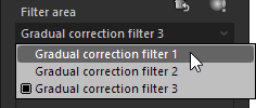 By repeating steps (1)~(4), a new area will be added to the “Filter area” as follows: “Gradual correction filter 2,” “Gradual correction filter 3,” etc.
* You can control areas one by one on the image.
Therefore, when you have multiple designated areas, you can perform operations by switching areas of operation in the “Filter area.”
4.18.2.3. Brush area
4.18.2.3.1. Add new brush
Activate the “Partial Correction Tool” sub-control and click
.
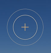 A double circle cursor will be displayed on the preview.
The inner circle indicates the area where the effect is strongest and the outer circle indicates the area where the effect becomes weaker.
Set the “Brush size” and “Feather” in advance according to the area to be corrected, and drag on the preview to draw the brush.
The drawn area will be displayed in red.
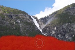
When you release the mouse, the item of that area will be added as the “Brush area 1” to the “Filter area.”
After setting the area, operate each item in the “Partial correction tool” sub-control to make your corrections.
If you want to make adjustments to another area, follow steps (1)~(4) making a new area for a gradual correction filter.
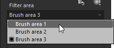 By repeating steps (1)~(4), a new area will be added to the “Filter area” as follows: “Brush area 2,” “Brush area 3,” etc.
* If you want to add a brush drawing or delete a part of the red region, use “d. Add brush to the selected filter area” or “e. Brush eraser.”
* You can control areas one by one on the image.
Therefore, when you have multiple designated areas, you can perform operations by switching areas of operation in the “Filter area.”* You cannot change the size of the Brush area.
4.18.2.3.2. Add brush to the selected filter area
This mode is activated when a brush area is selected in “Brush area.”
Activate the “Partial Correction Tool” sub-control and click
.
A double circle cursor will be displayed on the preview. The inner circle indicates the area where the effect is strongest and the outer circle indicates the area where the effect becomes weaker.
In addition, the brush area already written will be displayed in red.
Make additional corrections to the Brush that has already drawn.
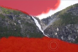 Set the “Brush size” and “Feather” ahead of time according to the area to be corrected, and draw the Brush by dragging on the Preview.
The drawn area will be displayed in red.
When you have completed your additions, click on the
button again.
The Brush Edit Mode will be cancelled and the corrected area will be added to the selected “Brush area.”
4.18.2.3.3. Brush eraser
This mode is activated when a brush area is selected in “Filter area.”
Activate the “Partial Correction Tool” sub-control and click
.
A double circle cursor will be displayed on the preview.
The inner circle indicates the area where the effect is strongest and the outer circle indicates the area where the effect becomes weaker.
In addition, the brush area already written will be displayed in red.
Portions of the Brush already drawn will be cancelled.
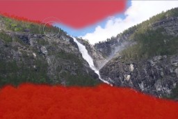 Set the “Brush size” and “Feather” ahead of time according to the area to be corrected, and erase the red area by dragging on the Preview.
When you have completed your additions, click on the
button again.
The Brush Edit Mode will be cancelled and the parts of the corrected area will be removed from the selected “Brush area.”* If deleting from the entire Brush area, please use “Delete selected filter area”.
4.18.2.4. Curve / Polygon area
Activate the “Partial correction tool” sub-control and click “Add curve”
or “Add polygon” .Click on the preview to add points. When three or more points are added, a curve or polygon connecting the points will be displayed.
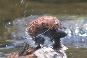 Click on the preview around the range you wish to correct.
Right-click to delete the last point you set.
Double-click at the end to confirm the set area(*1).
This area is added to “Filter area” as an item named “Curve area 1” or “Polygon area 1”.
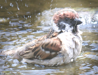 The designated area is displayed as a curve or polygon connecting points.
You can make fine adjustments to the area by operating the center or points of the area.
Right-clicking on a point will delete it.
Once an area is set, operate the items in the “Partial correction tool” sub-control to perform correction.
If there are more areas you wish to adjust, perform steps (1) through (5) to create a new curve or polygon area to operate.
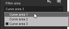 Each time you repeat steps (1) through (5), a new area will be added to “Filter area” (e.g., “Curve area 2”, “Curve area 3”, and so on).
*1 Curve and polygon areas cannot be set in a way in which sides intersect.
If there are intersecting sides when points are added, the color of the curve or polygon will change to pink, so make sure there are no intersecting sides when confirming the area.
4.18.3. How to use adjustment using “Select color to be corrected”
By using the “Select color to be corrected” function on a filter area, you can specify an area in an image and change the color of only that area, or retain only certain colors and turn the other areas into monochrome.
Here, we will introduce an example of how to make adjustments using the “Select color to be corrected” function on a filter area.
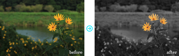
How to make adjustments using 'Select color to be corrected'
Adjustment steps
Add a filter area by encircling the area to be corrected.
In this example, a flower drawn with a brush is set as an area to be corrected.
If you add a filter area, the entire specified area will be set to be lighter at first.
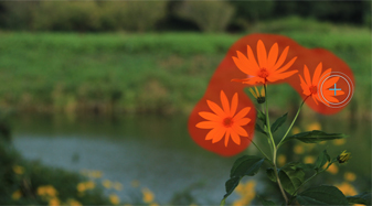
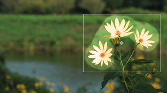
Switch to the “Select color to be corrected” tab and set the color to be corrected.
The color to be corrected can be specified using any of the following three methods.- Select an approximate color from the “Select color” dropdown list
- Select a color in an image using the “Color selection tool”
- Set a value directly using the “Hue” slider in the “Select color to be corrected” tab
By directly selecting a color in an image using the “Color selection tool”, you can make adjustments intuitively.
Here, we will select the petal area using the “Color selection tool”.
“Select color to be corrected” will be enabled, and the color selected as the color to be corrected will be set.
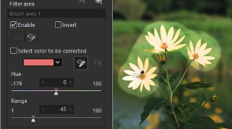
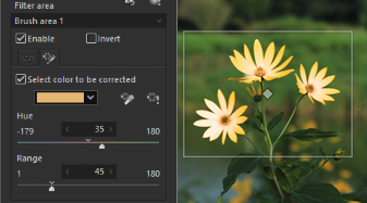
- Select an approximate color from the “Select color” dropdown list
By clicking “Preview of selected color”, you can check the selected color on the preview image(*).
The area shown in color is the selected color.
In this example, the tip of the petal is not completely inside the selected color area, so the “Range” slider value will be increased so that the petal will be shown entirely in color.
The selected color has now been set.
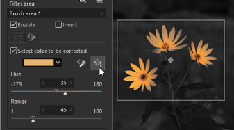
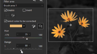
* Note that the “Preview of selected color” function is a function for displaying areas other than the selected area in monochrome, and is not an adjustment parameter.
Clear “Preview of selected color” and adjust parameters.
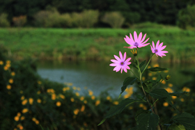 The example on the right shows the flower area in a different color by adjusting the “Hue” and “Saturation”.
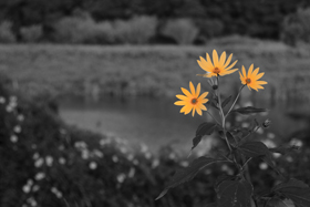 The example on the right shows the image with the selected color inverted by placing a check in “Invert”, after completely removing the saturation of the flower area by setting “Saturation” to -100.
Color is retained only in the flower area, with all other areas in monochrome.
4.19. Editing history
You can return or go forward to different edited conditions for the selected image with the toolbar’s  ,
,  or with [Undo] and [Redo] under [Edit (E )] in the menu.
Also by using “Editing history” sub-control, you can check the list of edited history for the selected representative image, and re-operate the part of history.
* Please see “7.7. Operations for Multiple Selected Images” concerning the representative image.
4.19.1. “Editing history” sub-control
 The menu command [View (V)]-[Sub-controls]-[Editing history] displays the “Editing history” sub-control.
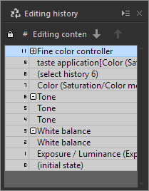 Operations for editing and the history of development parameters for representative images are displayed in the “Editing history” sub-control.
Operation contents, such as “Exposure bias” and “Color” are arranged in an easy to see format and are collected by category.
Up to 100 histories of edited contents are saved for each image. When edited contents exceed that number, old contents are deleted, and the most recent 100 histories are saved.
4.19.1.1. Operation Methods
Undo/Redo of representative image
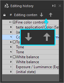 You can go back and forth to edited conditions for selected representative images using the
  and
and  functions in the “Editing history” sub-control.
Selecting history
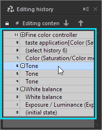 You can restore edited contents of selected locations by clicking on displayed history items.
Protecting history
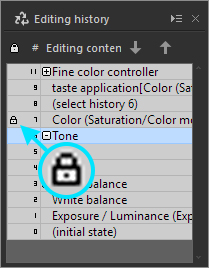 Editing contents are automatically deleted when they exceed the regulated amount.
Therefore, you can set “Protect” to protect special edited contents so they will not be automatically deleted.
Click on the left side of the history number on each edited content to protect it. A “Protect” mark is shown.
Click on the “Protect” mark again to remove protection. The mark will be removed.
Selecting histories displayed in the reference preview
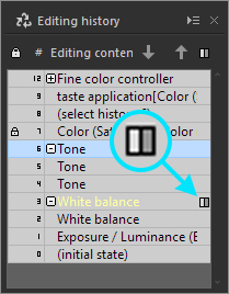 If the multi preview is in the reference preview mode, you can apply an edited content to the display of reference preview.
 is displayed when the mouse cursor is moved to the right side of the edited contents for the display.
The designated edited contents are applied in the reference preview when you click on the designated edited contents under these conditions.
*
, which is always displayed, means that this edited content is displayed as a reference preview.
4.20. Image properties
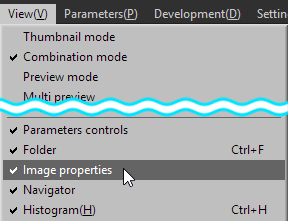 Change properties of currently selected image
Select [View (V)]-[Image properties] from the menu.
This can be displayed by clicking on ![]() in the main control.
in the main control.
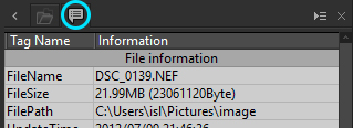
The “Image Properties” sub-control is also a control for viewing image property information, but there is also a function for simultaneously editing image properties.
If photographic information recorded in the RAW data is incorrect, you can correct it or add information not recorded.
You can edit comments here.
You can also add information based on IPTC (International Press Telecommunications Council).
You can also make settings that do not record only specific information.
Contents edited here are recorded in JPEG / TIFF images development results by SILKYPIX .
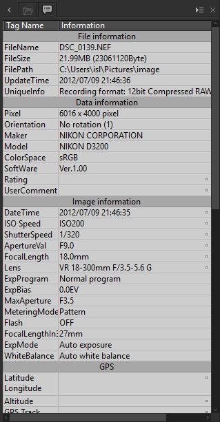
Image Properties
4.20.1. File information
File information for the selected image file is displayed.
Editing is not available for items in this category.
Information related to the file format is displayed in “UniqueInfo”.
Refer to this information when a selected image is not shown in the preview display, because information may be displayed if it is a format not supported by SILKYPIX or if the file is corrupted.
“Editing date and time” displays the date and time of the latest edit by SILKYPIX.
This is the edit date and time development parameter that SILKYPIX automatically records. It is not displayed for images that have not had development parameters edited or for initial development parameters.
4.20.2. Data information
This is mainly information recorded in Exif information for RAW data and JPEG / TIFF images. Information related to the image and secondary information on the image is displayed here.
“UserComment” and “Rating” are items that can be edited.
4.20.3. Image information
This is mainly information recorded in Exif information for RAW data and JPEG / TIFF images. Photographic information such as camera settings at the time the photograph was taken is displayed here.
“DateTime”, “ISO Speed”, “ShutterSpeed,” “ApertureVal”, “FocalLength” and “Lens” can be edited.
You can freely edit items such as corrections to incorrect dates and times set on the camera or when photographic information is not correctly recorded such as when you use a manual lens.
When recording to a developed JPEG / TIFF image, the “Name of Lens Used” is recorded in a standard format to XMP, while other information is recorded as Exif information.
4.20.4. GPS
Positional information such as from GPS is chiefly found in information recorded in RAW data and Exif information in JPEG/TIFF images.
It is possible to edit each item.
4.20.5. IPTC
Information is edited based on IPTC (International Press Telecommunications Council).
If IPTC information is recorded to RAW data or JPEG / TIFF images under IPTC standards and/or XMP standards, it is displayed as initial values.
If recorded to developed JPEG / TIFF images, it is recorded under a format based on both IPTC and XMP standards.
4.20.6. Editing Items
Some image property items can be edited.
Edited contents are reflected in additional information when saved to developed JPEG / TIFF images.
Utilize this for corrections to image property recorded in RAW data, for adding unrecorded information or if not recorded as additional information when saving developed JPEG / TIFF images.
Items that can be edited have one of the following icons displayed on the right side of “Information.”
Items that do not show an icon cannot be edited.
 : Show items that are unedited from their initial values.
There are some cases where initial values are not set.
: Show items that are unedited from their initial values.
There are some cases where initial values are not set. : Show edited items.
 : Show items where the “Do not record when developing” setting was explicitly performed.
This item is not recorded as secondary image information when saving developed JPEG / TIFF images.
: Show items where the “Do not record when developing” setting was explicitly performed.
This item is not recorded as secondary image information when saving developed JPEG / TIFF images.
To edit an item that can be edited, place the mouse over the item and click on  displayed on the left side, or double click on the “Information” cell.
An edit item dialog will appear.
4.20.6.1. Edit Item Dialog
The contents of the edit item dialog edit item dialog may slightly differ depending on the image property item, but the following are common operations.
Edit item contents
Set optional item contents.
The setting format may slightly differ depending on the type of item.
Enter characters in the text box for characters.
There are also some items for which you can choose values from a dropdown list.
“Datetime” is a special case, so please refer to “4.20.6.2. DateTime”.Select item contents from edit history
If there are items that can be set with optional values, you can choose item contents from the edit history up set to that time.
Use this if you set the same information repeatedly, such as IPTC information items and the name of your lens.Initialize
Return to unedited status.When developing, non-record
Items with this check box checked will not record secondary image information when saving developed JPEG / TIFF images.
Items without initial values set are checked in their initial status.
You can explicitly make a setting for items that you do not want to record as secondary image information when saving developed JPEG / TIFF images.
4.20.6.2. DateTime
“DateTime” takes special handling, so it will be explained here separately.
The “DateTime” setting is used mainly for corrections to “<DateTime” when the date and/or time of the photograph recorded by the camera is incorrect.
The set “DateTime” manages time differences in consideration of correcting the date and/or time the photograph was taken for all photographs taken, such as when the time set on the camera is not correct.
Therefore, you can correct the “DateTime” at one time by editing the “DateTime” on one image and copying the contents onto other images.
Use Change Date / Time of file as the default “DateTime” for image processing images that do not have “DateTime” recorded such as images read by scanners.
In this case “(Date / Time changed)” is added to the end of the “DateTime” item in “Image Properties”.
4.20.7. IPTC Information Taste
You can create tastes for IPTC information.
You can easily recall them by recording IPTC information you often use as a “Taste.”
Please see “4.1.1. Taste” for details on how to use tastes.
4.20.8. Register lens name
This function is for recording lens names.
Depending on the camera and lens you use, there may be times when the lens name displayed is different from the lens you use, such as when your lens is from a third-party manufacturer.
In this case, you can record the lens name in order to lessen the trouble it takes to change the lens name every time.
Enter the lens name you want to register in the lens item editing dialog and push “Register.” Later, the registered lens name will be displayed.
This function can be used only in cases when you can obtain information that can distinguish lens from the image data.
There are cases when this function cannot be used, depending on the camera and lens. The edit item dialog for the lens to “Register” will be on when it can be used.
4.21. Other
4.21.1. Setting On / Off
Some settings within the development parameters can be set “On / Off.”
The “On / Off” settings can be found in the following sub-controls.
Fine color controller
Lens aberration controller
Rotation/Shift lens effect
Effects
Monochrome controller
In “Fine color controller”, the “On / Off” settings for the development parameters of the entire sub-control will be switched.
In other sub-controls, the “On / Off” settings for development parameters will be switched for each adjustment item with a “On / Off” setting in each block.
If parameter blocks are off, they will have equal status no matter what value is used in the development parameters composed of the parameter blocks.
4.21.2. Dynamic default
This function changes some of default parameters to values our company deems optimal, based on the camera model (such as the type and size of an image sensor and a resolution), as well as information at the time of shooting in the RAW data (such as ISO film speed).
Initial settings for WB shooting information, lens distortion bias from angle of view shading, angle of view digital shift from Rotation/Shift lens effect, Sharpening (Outline emphasis, Ringing artifact ctrl.), Noise reduction (color distortion, smoothness), Development settings (demosaicing sharpness) and highlight controller (Luminance restoration and dynamic range) are dynamically changed. (*)
This function is enabled when the default parameter is “Default”.
To enable the dynamic default in other tastes, you prepare a partial taste that does not adjust parameters which are adjusted by the dynamic default and then you use the prepared one as the default parameter.
In addition, the initial cropping area of the developed image is also changed dynamically in accordance with the aspect ratio set on a camera. Please refer to the “4.14.5. How to handle the RAW data with the aspect ratio set on a camera” for more detail.
Moreover, when the lens profile of lens distortion bias is enabled and an appropriate lens profile could be identified, the manufacturer and lens of the lens profile will be automatically selected as default parameters.
By employing this function, SILKYPIX gives recommendations based on information at the time of shooting for the initial settings of each parameter listed above from the status at the time the photograph (RAW data) was read and first opened. Therefore, even when performing finishing work on adjusting parameters as a post-process, you can start from the status of making adjustments that meet each of the shooting conditions so that you can proceed smoothly.
* In some models, other dynamically changing parameters may exist.
4.21.3. Keyboard and Mouse Operation for macOS
This manual is described on the assumption that the mouse has 2 or more buttons and keyboard operation is for Windows PC.
Therefore if you use macOS PC, please pay attention for the following;
Right click
[Control] key + mouse click is the same as “Right click” of the mouse.[Ctrl] key + Left click
[Command] key + mouse click is the same as “[Ctrl] key + Left click” of the mouse.[Alt] key
[Option] key is the same as [Alt] key.